Complete Guide to Steam Turbine Operation and Maintenance: From Startup to Shutdown
Why Steam Turbines Are the Workhorses of Power Generation
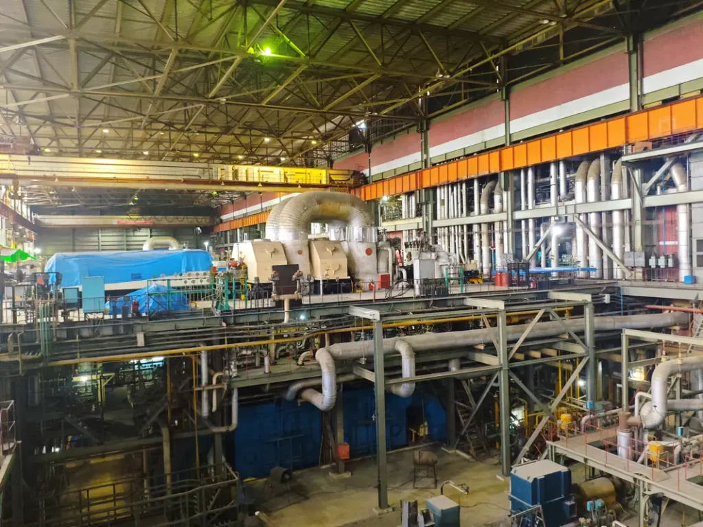
Walk into any major power plant around the world, and you’ll hear it—the distinctive hum of massive steam turbines converting thermal energy into electricity. These mechanical giants generate approximately 80% of the world’s electricity, making them the true workhorses of modern civilization.
Yet despite their ubiquity, steam turbines remain mysterious to many new power plant engineers. The complexity can be overwhelming: thousands of components working in harmony, operating parameters that must be precisely controlled, and maintenance requirements that demand both technical expertise and operational intuition.
Many new engineers harbor misconceptions about steam turbine operations. Some believe that once started, turbines run themselves. Others assume that modern digital controls eliminate the need for operator skill. The reality is more nuanced: while technology has improved safety and efficiency, successful steam turbine operation still requires deep understanding of thermodynamics, mechanical systems, and operational judgment that only comes through experience.
Your roadmap to mastering steam turbine operations starts here. This guide will take you from fundamental principles through advanced troubleshooting, providing the practical knowledge needed to operate these magnificent machines safely and efficiently.
Decoding the Steam Turbine: What’s Really Happening Inside
A. The Magic of Steam Expansion (But It’s Actually Physics)
Steam turbines operate on a deceptively simple principle: high-pressure, high-temperature steam expands through carefully designed nozzles and blade passages, converting thermal energy into mechanical rotation. Think of it as controlled expansion—we’re harnessing steam’s natural desire to expand and cool.
The process begins when superheated steam at around 1000°F and 2400 psi enters the turbine. As it expands through successive stages, pressure and temperature drop while volume increases dramatically. By the time steam reaches the condenser, it may be at 1 psi absolute—a pressure reduction of over 99%.
Confusion Buster Box: “Why do we need so many stages? Can’t one big stage do it all?”
Let me break down this physics concept step by step.
When steam expands from high pressure (like 2400 psi) to low pressure (like 1 psi) in a single stage, the available energy creates enormous acceleration. The steam wants to expand according to thermodynamic laws, and if we allow it to do so all at once, it reaches extremely high velocities.The Velocity Calculation:
Using the basic energy equation for steam expansion, if we expanded from 2400 psi at 1000°F down to 1 psi in one step, the theoretical steam velocity would be:
V = √(2 × ΔH)
Where ΔH is the enthalpy drop (energy available). For this expansion, that velocity approaches 4000-4500 ft/sec, which is roughly 3 times the speed of sound in steam (around 1500 ft/sec at these conditions).
Why Supersonic Velocities Are Problematic:
- Shock Wave Formation: When steam exceeds sonic velocity, shock waves form. These create sudden pressure and velocity changes that actually waste energy as heat and noise rather than useful mechanical work.
- Blade Design Impossibility: Turbine blades designed to handle 4000+ ft/sec steam would need to be incredibly robust but also aerodynamically shaped to manage supersonic flow. The mechanical stresses would be enormous, and the blade angles required would be impractical.
- Energy Loss Through Heat: At supersonic velocities, much of the kinetic energy converts to heat through friction and shock waves rather than rotating the turbine blades.
- Exit Velocity Waste: Even if we could capture some energy, steam would exit the turbine at extremely high velocity, carrying away significant unused kinetic energy.
The Multi-Stage Solution:
Instead, we break the expansion into stages where each stage handles a smaller pressure drop:
- Stage 1: 2400 psi → 1800 psi (manageable velocity ~800 ft/sec)
- Stage 2: 1800 psi → 1300 psi (manageable velocity ~900 ft/sec)
- And so on…
Each stage operates with reasonable steam velocities (600-1200 ft/sec) that turbine blades can efficiently capture. The cumulative effect extracts the same total energy, but in manageable increments.
Think of it like walking down a steep hill versus jumping off a cliff – both get you to the bottom, but only one allows you to control the process and arrive safely.
B. Meet the Key Players in Your Turbine
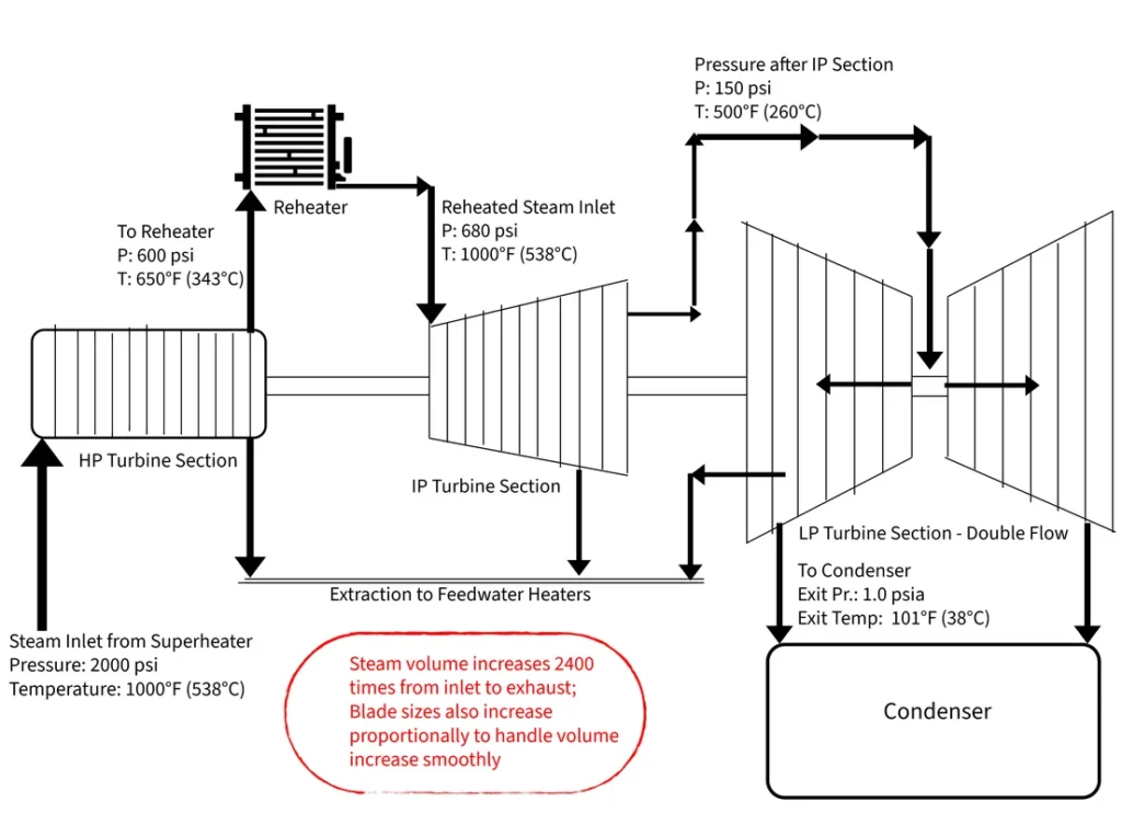
Modern steam turbines typically consist of three main sections, each with distinct characteristics:
High-Pressure (HP) Section: The muscle of the steam turbine operation, handling initial steam expansion from boiler pressure down to about 600 psi. These sections are compact, heavily built, and operate at the highest temperatures. Blade sizes are relatively small due to high steam density.
Intermediate-Pressure (IP) Section: The workhorse that handles reheated steam from about 600 psi down to 150 psi. After expansion through the HP section, steam returns to the boiler for reheating before entering the IP section—this reheat cycle improves overall plant efficiency.
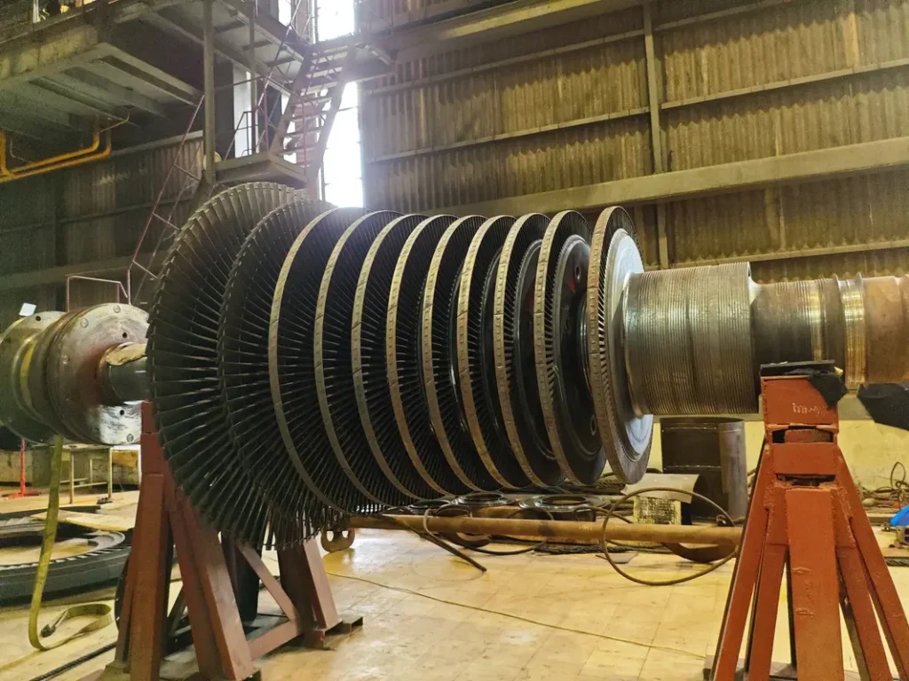
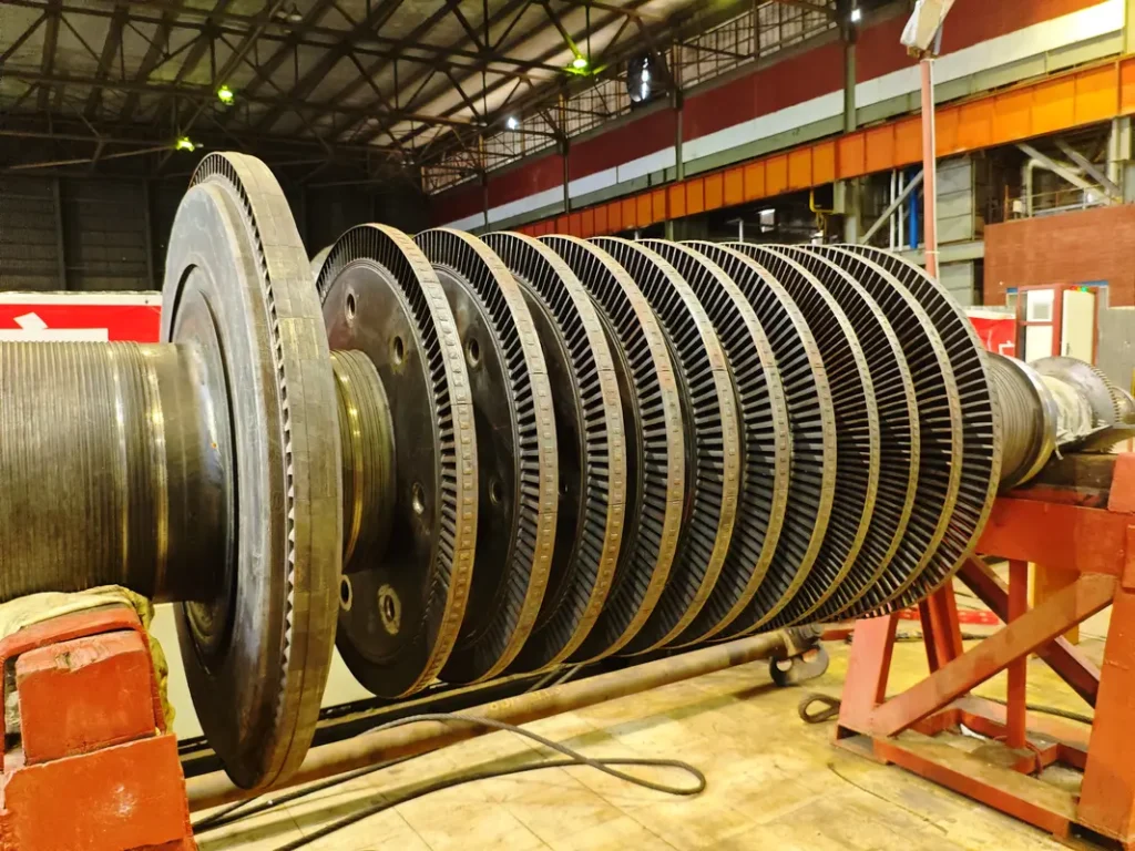
***Notice: Blade size is increasing to the steam downstream path (right to left) to deal with gradual steam expansion
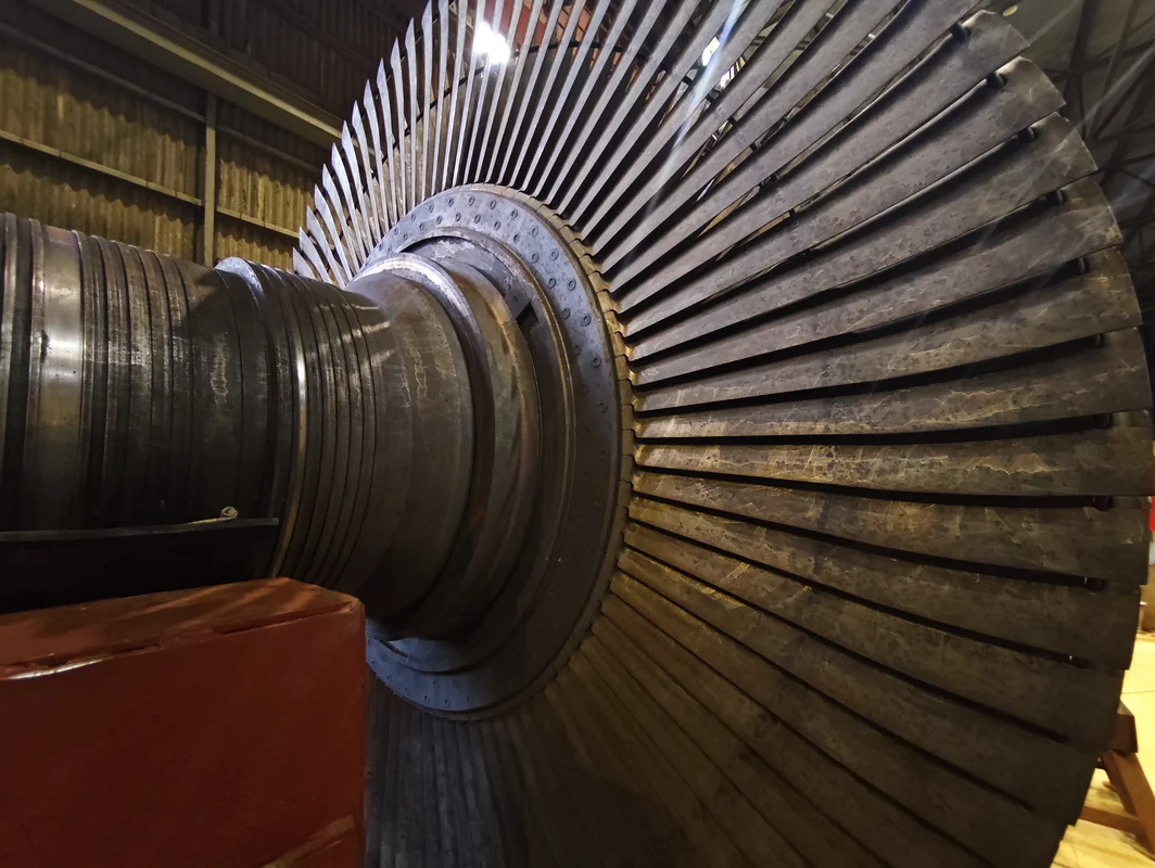
Low-Pressure (LP) Section: The volume handler, where steam expands from about 150 psi down to condenser pressure. LP sections feature the largest blades (often over 40 inches long) to handle enormous steam volumes at low pressure.
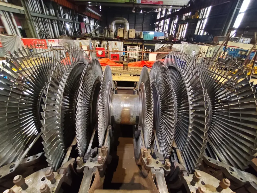
***Notice: Huge Blades are set to deal with high volume steam at low pressure
The rotor assembly represents precision engineering at its finest. Modern turbine rotors are forged from premium alloy steels and machined to tolerances measured in thousandths of an inch. Each blade row is precisely positioned to extract maximum energy while maintaining mechanical integrity under tremendous centrifugal forces.
Steam sealing systems deserve special attention—they prevent steam leakage while allowing the rotor to operate freely. Labyrinth seals create a tortuous path for steam, using pressure drops across multiple restrictions to minimize leakage. These systems must be properly maintained to prevent efficiency losses and potential safety hazards.
Before You Even Think About Starting: The Art of Preparation
A. The Detective Work: Pre-Start Inspections
Visual Inspection Checklist:
- Steam Line Integrity: Check for leaks, unusual deposits, or corrosion on main steam and reheat lines
- Oil System Condition: Look for stains, drips, or discoloration around bearings and oil lines
- Coupling Alignment: Verify coupling guards are properly positioned and no visible misalignment exists
- Foundation Integrity: Check for cracks, settling, or unusual gaps in foundation and supports
- Insulation Condition: Ensure thermal insulation is intact with no missing sections or damage
Instrumentation Verification:
- Temperature Sensors: Verify all bearing, metal, and steam temperature readings are reasonable and responsive
- Pressure Transmitters: Check steam, oil, and cooling water pressure indications for proper operation
- Vibration Monitors: Test vibration monitoring system and verify baseline readings
- Level Indicators: Confirm oil tank, condenser hotwell, and other level measurements are accurate
- Control System Response: Test governor, protection, and monitoring systems for proper response
Auxiliary Systems Readiness:
- Lubrication System: Oil tank filled, filters clean, pumps operable, oil temperature above 40°F
- Steam Seal System: Steam supply available, drainage clear, pressure regulation functional
- Cooling Water Systems: Flow established, temperatures normal, strainers clean
- Vacuum System: Ejectors ready, condenser isolated, vacuum pumps operational
- Electrical Systems: All motors energized, control power available, protection systems active

B. Safety First, Second, and Always
Protection System Verification:
- Overspeed Governor: Test mechanical and electronic overspeed protection systems
- Vibration Protection: Verify all vibration monitors are active with correct trip settings
- Temperature Protection: Confirm bearing and metal temperature alarms are functional
- Pressure Protection: Check lubricating oil and steam pressure protection systems
- Emergency Stops: Test all emergency turbine shutdown buttons and verify they function properly
Personnel Safety Preparation:
- Lockout/Tagout: Verify all turbine maintenance locks removed and systems returned to service
- Personal Protective Equipment: Ensure all personnel have required safety gear
- Communication Systems: Test all communication equipment and emergency notification systems
- Escape Routes: Confirm all emergency exits are clear and accessible
- Fire Protection: Verify fire suppression systems are armed and ready
Emergency Procedure Review:
- Trip Response Procedures: Review actions for various automatic trip scenarios
- Manual Shutdown Procedures: Confirm all operators know emergency turbine shutdown sequences
- Equipment Isolation: Verify ability to quickly isolate steam, oil, and cooling systems
- Emergency Contacts: Confirm all emergency contact information is current and accessible
The investment in thorough preparation pays dividends throughout the turbine startup process. Experienced operators know that 90% of startup problems can be prevented through methodical pre-start verification. The remaining 10% are usually discovered and corrected quickly when operators have confidence in their preparation work.
Remember: Starting a steam turbine without proper preparation is like performing surgery without sterilizing instruments—technically possible, but the consequences of shortcuts can be catastrophic.
Startup Secrets: From Cold Metal to Spinning Giant
A. Cold Start Chronicles: Patience is a Virtue
Think of a cold steam turbine like a massive steel giant that’s been sleeping in a cold room all night. Just as you wouldn’t jump out of bed and immediately run a marathon, this 100-ton machine needs time to wake up gradually. The turbine casing, constructed from thick steel sections, heats and expands slowly. Rushing this process creates thermal stresses that can crack casings or cause blade rubs that destroy rotating components.
The Foundation: Getting Ready to Wake the Giant
Step 1: Prepare the Life Support Systems Before any steam touches the turbine, its support systems must be running perfectly:
- Oil circulation starts flowing – Like getting blood flowing to warm up your muscles
- Steam seals get their steam supply – Prevents air from sneaking into the turbine
- Condenser vacuum begins building – Creates the “suction” that helps steam flow through
The oil temperature must reach at least 40°F. Cold oil is like thick honey – it won’t protect bearings properly. This isn’t negotiable; damaged bearings cost millions and months to repair.
The Warming Dance: Teaching Metal to Expand
Step 2: Steam Warming Process Picture the turbine as a thick-walled steel fortress that’s been sitting in winter cold. When you introduce hot steam (1000°F) to cold metal (maybe 50°F), the metal wants to expand rapidly. But thick steel sections expand slowly on the outside while heating quickly on the inside, creating dangerous stress.
The warming process works like this:
- First touch: Steam enters drain lines and dead-end piping to warm them up
- Gradual admission: Small amounts of steam slowly warm the main steam lines
- Patient progression: Steam temperature gradually increases while monitoring metal expansion
Why the patience? Metal expands at different rates. The thin steam pipes heat quickly, but the massive turbine casing heats slowly. If you rush, the differential expansion can crack the casing or cause rotating parts to rub against stationary parts – both catastrophic failures.
The Critical Numbers
Target heating rate: 100°F per hour maximum
- Faster heating = thermal stress = cracked metal
- Slower heating = wasted time but safe operation
- Monitor expansion measurements continuously
Differential expansion limits:
- Rotor expands faster than casing (it’s smaller and heats quicker)
- Must stay within 0.020″ differential during warming
- Exceed this limit = blade tips rub casing = destroyed turbine
Speed Ramping: From Standstill to Spinning
Step 3: The First Revolution Once metal temperatures stabilize, the actual rotation begins:
200 RPM – The Oil Film Builder
- Establishes protective oil films in all bearings
- Allows operators to verify no unusual noises or vibrations
- Turning gear disengages automatically at this speed
900-1100 RPM – The Critical Speed Sprint
- This is the turbine’s “critical speed” where natural vibrations amplify
- Must pass through quickly (like pushing a swing at just the right moment)
- Lingering here causes destructive resonant vibrations
1800 RPM – The Stability Check
- Hold here for several minutes
- Listen for unusual sounds
- Verify all temperatures and vibrations are normal
3000 RPM – Ready for Business
- Synchronous speed for 60 Hz electrical generation
- All systems stable and ready for generator synchronization
What You’re Really Watching
During this entire 4-6 hour process, operators monitor:
- Metal temperatures – Ensuring even heating without hot spots
- Differential expansion – Rotor and casing expanding together, not fighting each other
- Vibration patterns – Each turbine has a “fingerprint” of normal vibrations
- Steam quality – Wet steam can destroy blades in minutes
- Bearing temperatures – Early warning of lubrication problems
B. Warm and Hot Starts: The Express Lane
Warm starts (turbine metal temperature 200-400°F) and hot starts (above 400°F) allow accelerated procedures, but temperature differentials remain the governing factor. The key insight: heated metal expands faster, so thermal stress management becomes more critical even as timeline pressures increase.
Steam admission can begin more aggressively, but temperature monitoring intensifies. Metal thermocouples throughout the turbine provide real-time feedback on thermal conditions. Experienced operators learn to read these patterns, recognizing when components are ready for the next step.
Time savings come from reduced warming periods, not from ignoring thermal limits. A typical cold start requires 4-6 hours; warm starts might complete in 2-3 hours; hot starts in 1-2 hours. However, forcing faster schedules risks equipment damage that far exceeds any economic benefits from early synchronization.
Confusion Buster Box: “Cold start vs. Hot start vs. warm start: What’s the real difference and why does it matter?”
Cold Start: Metal temperature below 200°F
- Turbine has been shut down for 24+ hours
- Metal has cooled to near-ambient temperature
- Requires full warming process (4-6 hours)
Below 200°F: Metal expansion is minimal and predictable. The turbine behaves like it’s completely cold, requiring full warming procedures to prevent thermal shock.
Warm Start: Metal temperature 200°F to 400°F
- Turbine shut down for 8-24 hours
- Still retains significant heat
- Faster turbine startup possible (2-3 hours)
200°F to 400°F: Metal has already expanded significantly but isn’t at full operating expansion. You can skip some warming steps, but differential expansion between rotor and casing still needs careful monitoring.
Hot Start: Metal temperature above 400°F
- Turbine shut down for less than 8 hours
- Metal still near operating temperature
- Rapid turbine startup possible (1-2 hours)
Above 400°F: Metal is already close to operating expansion levels. The rotor and casing are nearly in their normal operating relationship, allowing much faster steam admission and loading.
C. The Final Steps: Synchronization and Loading
Step 1: Pre-Synchronization Checklist
- Turbine speed stable at 3000 RPM (50 Hz) / 3600 RMP (60 Hz)
- Steam parameters stable (pressure, temperature, flow)
- No active alarms or abnormal indications
- Generator excitation system energized and ready
- Automatic voltage regulator in service
- Main generator breaker verified open
- Protection systems armed and functional
Step 2: The Synchronization Dance
Understanding What Must Match: Your generator must perfectly match the electrical grid on three critical parameters before connecting:
Frequency Matching (Speed Control):
- Grid frequency: Exactly 60.00 Hz or 50.00 Hz (depending on North America or Asia)
- Generator frequency: Must match within 0.1 Hz
- Adjustment: Fine-tune steam admission through governor control
- Watch: Synchroscope needle rotation slows as frequencies approach match
Voltage Matching:
- Grid voltage: Typically 16-20 kV (varies by plant)
- Generator voltage: Must match within 5%
- Adjustment: Increase or decrease generator excitation
- Watch: Voltage differential meter approaches zero
Phase Angle Matching:
- Both systems must be “in phase” (peaks and valleys aligned)
- Synchroscope shows phase relationship
- When needle points to 12 o’clock: Perfect alignment
- Connection window: ±10 degrees maximum
The Synchronization Process:
- Coarse Adjustment (Manual Mode):
- Adjust governor to bring frequency within 0.5 Hz of grid
- Adjust excitation to bring voltage within 10% of grid
- Monitor synchroscope for slow, steady rotation
- Fine Tuning:
- Reduce frequency difference to less than 0.1 Hz
- Fine-tune voltage to exact match
- Watch synchroscope needle slow down
- The Connection Moment:
- Synchroscope needle approaching 12 o’clock position
- All parameters within limits
- Close main generator breaker
- Critical: Must close breaker within the brief alignment window
Modern Automatic Synchronizers:
- Verify auto-sync system is armed
- Check permissive conditions are met
- Monitor system automatically adjusting speed and voltage
- Stand ready to take manual control if needed
Step 3: Initial Loading – The First Steps
Immediate Post-Connection Actions:
- Verify successful synchronization (no large current transients)
- Confirm generator is actually connected (real power > 0 MW)
- Monitor all electrical parameters for stability
- Check mechanical parameters remain normal
First Load Application (0-10 MW):
- Why start small: Allows verification that all systems respond properly
- Steam adjustment: Slightly open control valves to increase steam flow
- Governor response: Should automatically adjust to maintain 60 Hz
- Monitor closely: Any unusual vibrations, temperatures, or sounds
Key Parameters to Watch:
- Generator real power output (MW meter)
- Generator reactive power (MVAR meter)
- Steam flow increase proportional to load
- Turbine speed remains at exactly 3000 RPM
- All temperatures responding normally
Step 4: Gradual Loading Process
Loading Rate Guidelines:
- Target rate: 3-5 MW per minute maximum
- Why gradual: Allows thermal adjustment of all components
- Steam system response: Boiler must match increased steam demand
- Mechanical monitoring: Watch for any developing problems
Step 5: What to Watch During Loading
- Unusual vibrations: Could indicate mechanical problems developing
- Temperature excursions: May suggest cooling or lubrication issues
- Pressure variations: Might indicate steam quality or flow problems
- Performance deviations: Could reveal steam path restrictions
- Electrical anomalies: May suggest generator or excitation problems
Step 6: Reaching Full Load
- Verify target load reached
- Check all parameters stable and within normal ranges
- Check efficiency at expected levels for current conditions
- Check no active alarms or abnormal indications
- Optimize steam conditions for maximum efficiency
- Check protection systems remain active and set correctly
- Notify system operators of successful unit startup
Mastering Daily Operations: Reading Your Turbine’s Mind

Daily Monitoring Table: Steam System Parameters
| Parameter | Freque-ncy | Normal Range | Warning Level | Critical Level | Root Causes | Immediate Action |
|---|---|---|---|---|---|---|
| Main Steam Pressure | Every hour | 2350-2450 psi | 2200-2350 or 2450-2500 psi | <2200 or >2500 psi | Boiler issues or demand changes | Check boiler operation, coordinate with operators |
| Main Steam Temperature | Every hour | 995-1005°F | 980-995 or 1005-1020°F | <980 or >1020°F | Superheater control problems | Verify boiler superheat control |
| Reheat Steam Pressure | Every hour | 580-620 psi | 550-580 or 620-650 psi | <550 or >650 psi | Reheater system issues | Check reheat steam path |
| Reheat Steam Temperature | Every hour | 995-1005°F | 980-995 or 1005-1020°F | <980 or >1020°F | Reheat control malfunction | Coordinate with boiler control |
| Steam Flow Rate | Continu-ously | Varies with load | ±10% sudden change | ±20% sudden change | Flow restriction or demand surge | Check valve positions and system demand |
| Steam Quality | Every 2 hours | Superheated | Reduced superheat | Saturated steam | Boiler water carryover | Reduce load, check boiler chemistry |
***values can differ for different machines
Daily Monitoring Table: Control & Auxiliary Systems
| Component | Check Point | Normal Condition | Warning Signs | Critical Signs | Root Causes | Corrective Actions |
|---|---|---|---|---|---|---|
| Governor System | Speed accuracy | ±0.25% of setpoint | ±0.5% deviation | ±1.0% deviation | Control system drift | Calibration check |
| Load Control | Response time | <5 seconds | 5-10 seconds | >10 seconds | Valve sticking | Exercise valves |
| Protection Systems | Status lights | All systems armed | One system down | Multiple systems down | Instrument failure | Immediate repair |
| Generator Output | MW meter | Matches steam flow | 5% deviation | 10% deviation | Electrical issues | Coordinate with electrical |
| Excitation System | Voltage regulation | ±2% of setpoint | ±5% deviation | ±10% deviation | AVR malfunction | Switch to manual |
| Frequency Control | Grid frequency | 50.00 ± 0.05 Hz | ±0.1 Hz | ±0.2 Hz | Grid disturbance | Coordinate with system ops |
| Condenser Vacuum | Vacuum gauge | 28-29″ Hg | <26″ Hg | <24″ Hg | Air ingress or leakage | Check cooling water, air leaks |
| Lube Oil | Pressure gauge | 20-30 psi header | <18 psi | <15 psi | Pump fault or filter jammed | Check pumps, filters |
| Steam Seals | Visual inspection | Light steam wisps | More than normal steam wisps | Heavy steam or no steam | Sealing system damage | Investigate and adjust |
***values can differ for different machines
Maintenance Mysteries Solved: Keeping Giants Running
Daily Turbine Maintenance Inspection Checklist Table
| Component | Inspection Point | Normal Condition | Abnormal Signs | Severity Level | Likely Cause | Maintenance Actions |
|---|---|---|---|---|---|---|
| Oil Sight Glasses | Flow visibility | Clear oil flow visible | No flow or foamy oil | Critical | Pump failure, air entrainment | Immediate investigation |
| Steam Glands | Steam leakage | Minimal wisps | Heavy steam or water | Moderate | Seal wear, pressure issues | Adjust seals, check pressure |
| Coupling Guards | Alignment/security | Centered, tight bolts | Loose or misaligned | High | Foundation movement | Stop unit, investigate |
| Drain Systems | Flow condition | Clear drainage | Backing up or excessive flow | Moderate | Trap failure, plugging | Clean traps, check piping |
| Insulation | Thermal protection | Intact, no hot spots | Missing sections, damage | Moderate | Age, vibration, maintenance | Repair insulation |
| Electrical Connections | Tightness, condition | Tight, no corrosion | Loose, overheated | High | Vibration, environment | Tighten, clean, protect |
Scheduled Turbine Maintenance: The Planned Interruptions
Lubrication system maintenance ensures reliable bearing protection. Oil filtration systems remove contaminants that cause bearing wear. Cooler cleaning maintains proper oil temperatures. Pump maintenance ensures adequate oil pressure and flow under all operating conditions.
Steam seal adjustments balance efficiency against reliability. Tight seals minimize steam leakage but risk rubbing during transient conditions. Loose seals prevent damage but reduce efficiency through increased leakage. Finding the optimal balance requires experience and careful measurement.
Instrumentation calibration maintains the accuracy essential for safe operation. Temperature sensors must read correctly to prevent overheating. Pressure transmitters must be accurate for proper control system operation. Vibration monitors must be sensitive enough to detect problems while avoiding false alarms.
Protection system testing verifies that safety systems will operate when needed. Overspeed trip testing ensures the governor will shut down the turbine at the correct speed. Vibration trip testing confirms that mechanical problems will trigger appropriate responses. These tests must be performed carefully to avoid equipment damage while ensuring system operability.
Predictive Turbine Maintenance Program: Your Safety Insurance
| Analysis Type | Sample/Da-ta Collection | Normal Results | Trending Concern | Critical Level | Root Cause Analysis | Maintenance Planning |
|---|---|---|---|---|---|---|
| Oil Analysis – Metals | Monthly oil sample | Fe <15ppm, Cu <5ppm, Cr <3ppm | 50% increase month-over-month | Fe >25ppm, Cu >10ppm, Cr >5ppm | Component wear identification | Schedule bearing inspection |
| Oil Analysis – Contaminati-on | Monthly oil sample | Water <200ppm, Particles <ISO 16/14/11 | Water increasing, particles up | Water >500ppm, Particles >ISO 20/18/15 | Seal leakage, filtration failure | Repair seals, upgrade filtration |
| Vibration Analysis | Spectral data | Amplitude stable, no new frequencies | New peaks, amplitude growth | Peaks >5x baseline | Mechanical looseness, wear | Plan outage repairs |
| Thermograp-hy | Thermal images | Temperatures uniform, no hot spots | Gradual temperature increase | >30°C above ambient | Electrical or mechanical issues | Schedule detailed inspection |
| Performance Testing | Heat rate calculation | Within design ±2% | Degrading >1% per month | >10% above design | Steam path fouling, leaks | Plan steam path maintenance |
| Steam Quality | Boiler chemistry data | Within specifications | Trending toward limits | Outside specifications | Water treatment issues | Coordinate with boiler maintenance |
When Things Go Wrong: Troubleshooting Like a Pro
Problem 1: High Bearing Temperature
What It Means: Your turbine bearings are getting too hot, which means they’re not being cooled or lubricated properly.
Symptoms:
- Temperature readings above 185°F (normal is 160-180°F)
- Temperature rising steadily over hours or days
- One bearing hotter than others
- Oil temperature at bearing drain increasing
Root Causes:
- Oil pump failure or reduced flow
- Dirty oil filters restricting flow
- Oil cooler fouling reducing cooling
- Bearing wear creating more friction
- Misalignment causing extra load
Immediate Actions:
- Reduce turbine load to decrease heat generation
- Check oil pressure and flow rates
- Start backup oil pumps if available
- Monitor temperature every 15 minutes
- Prepare for emergency turbine shutdown if temperature continues rising
Corrective Actions:
- Change oil filters if pressure drop is high
- Clean oil coolers to restore cooling
- Increase cooling water flow to oil coolers
- Schedule bearing inspection during next outage
- Perform oil analysis to check for wear metals
If Ignored:
- Bearing failure within hours
- Rotor damage requiring months to repair
- Complete turbine destruction possible
Problem 2: Excessive Vibration
What It Means: Your turbine is shaking more than normal, indicating something mechanical is wrong.
Symptoms:
- Vibration readings above 3.5 mils (normal is 0.5-3.0 mils)
- Vibration increasing over time
- Unusual sounds (grinding, squealing, knocking)
- Vibration felt in floor or handrails
- Different vibration pattern than usual
Root Causes:
- Blade fouling or damage creating unbalance
- Bearing wear or looseness
- Misalignment due to thermal expansion
- Foundation problems or loose bolts
- Steam flow disturbances
Immediate Actions:
- Note exact vibration levels and locations
- Check if vibration changes with load
- Listen for unusual sounds
- Verify all mounting bolts are tight
- Reduce load if vibration is severe (>7 mils)
Corrective Actions:
- Schedule detailed vibration analysis
- Plan blade cleaning during outage
- Check alignment during next inspection
- Tighten any loose foundation bolts
- Balance rotor if unbalance confirmed
If Ignored:
- Catastrophic bearing failure
- Blade destruction from rubbing
- Foundation damage
- Complete rotor destruction
Problem 3: Steam Quality Problems
What It Means: The steam coming from your boiler contains water droplets instead of being pure dry steam.
Symptoms:
- Steam temperature lower than expected
- Water coming out of steam seal drains
- Efficiency dropping suddenly
- Unusual sounds in steam lines (water hammer)
- Visible moisture in steam
Root Causes:
- Boiler water level too high
- Boiler chemistry problems
- Superheater tube leakage
- Boiler load changes too rapid
- Attemperator (spray water) malfunction
Immediate Actions:
- Reduce turbine load immediately
- Open all steam line drains
- Check boiler water level and chemistry
- Coordinate with boiler operators
- Monitor blade path for water erosion
Corrective Actions:
- Fix boiler water level control
- Correct boiler chemistry issues
- Repair superheater tube leaks
- Adjust attemperator operation
- Inspect turbine blades for erosion damage
If Ignored:
- Blade erosion and failure
- Steam line water hammer damage
- Complete loss of efficiency
- Turbine internal damage
Problem 4: Control System Malfunction
What It Means: The systems that automatically control your turbine aren’t working properly.
Symptoms:
- Turbine not responding to load commands
- Governor hunting (load oscillating)
- Protection systems giving false alarms
- Steam valves not moving properly
- Erratic speed or load control
Root Causes:
- Sensor calibration drift
- Control valve sticking or wear
- Electronic system failures
- Air or hydraulic system problems
- Software glitches or corruption
Immediate Actions:
- Switch to manual control if possible
- Test each control valve individually
- Check all sensor readings for accuracy
- Verify hydraulic/pneumatic pressures
- Document all abnormal behaviors
Corrective Actions:
- Recalibrate all control sensors
- Service sticky control valves
- Replace failed electronic components
- Clean and service hydraulic systems
- Update or reload control software
If Ignored:
- Loss of turbine control
- Potential overspeed condition
- Load swings damaging equipment
- Protection system failures
Problem 5: Condenser Vacuum Loss
What It Means: Your condenser isn’t creating enough vacuum, which reduces turbine power and efficiency.
Symptoms:
- Vacuum readings below 26 inches mercury
- Exhaust temperature increasing
- Turbine output declining
- Steam consumption increasing for same load
- Air ejector working harder
Root Causes:
- Cooling water flow reduced or temperature high
- Air leaking into condenser
- Condenser tubes dirty or plugged
- Steam ejector problems
- Condenser tube leaks
Immediate Actions:
- Check cooling water flow and temperature
- Start backup cooling water pumps
- Check air ejector operation
- Look for obvious air leaks
- Monitor exhaust temperature closely
Corrective Actions:
- Clean condenser tubes
- Repair air leaks in vacuum system
- Service steam ejectors
- Plug leaking condenser tubes
- Improve cooling water system operation
If Ignored:
- Severe efficiency loss
- Blade stress from high backpressure
- Potential blade failure
- Economic losses from poor performance
Turbine Shutdown Strategies: Bringing Giants to Rest
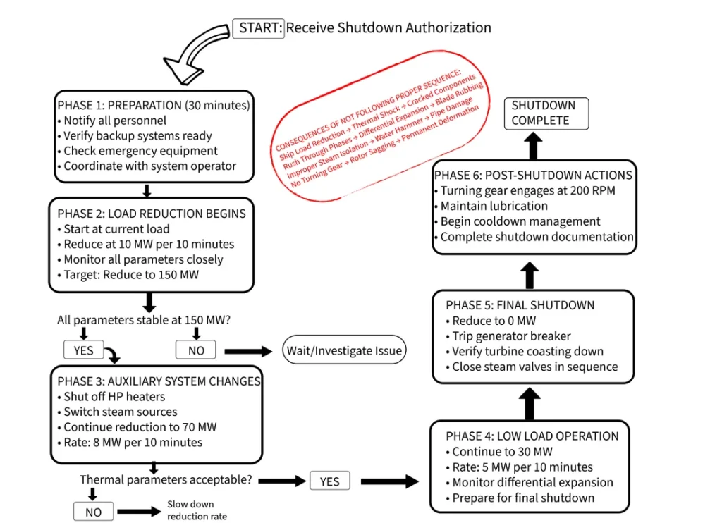
Planned Shutdown Flowchart
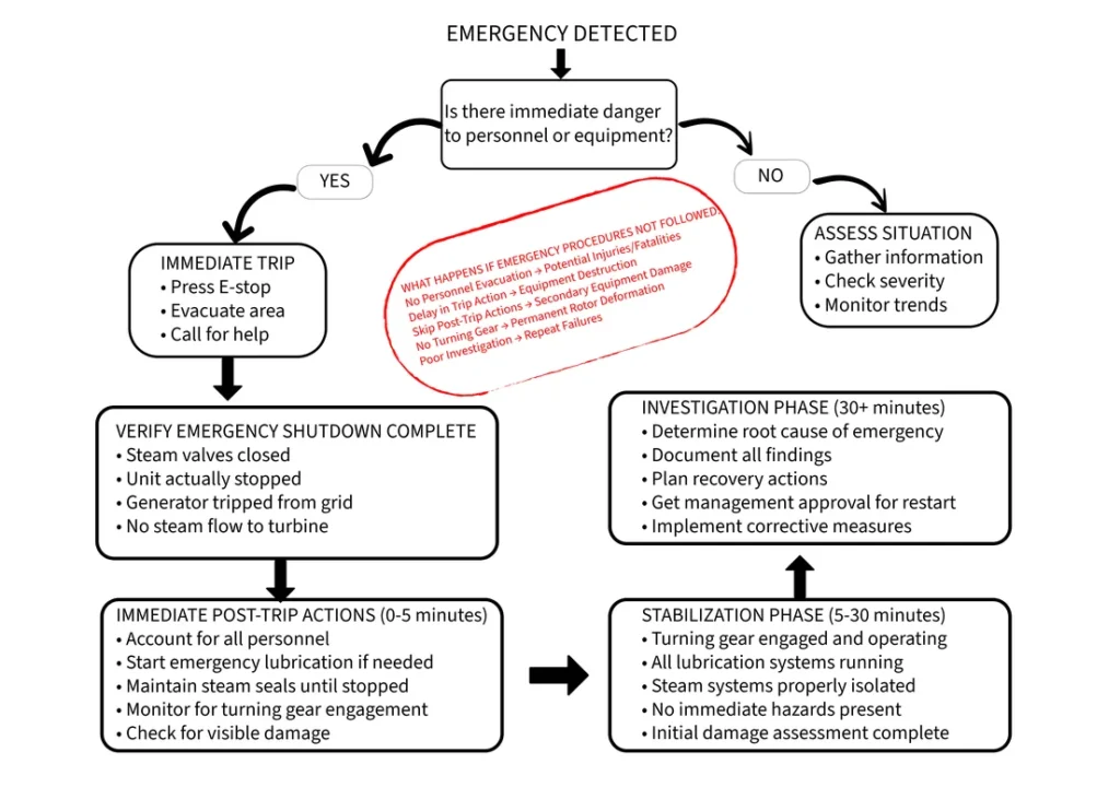
Emergency Shutdown Flowchart
Critical Shutdown Actions Checklist
Planned Turbine Shutdown – Must Do Items
Load Reduction Phase:
- Reduce load gradually (never exceed 15 MW per 10 minutes)
- Monitor differential expansion continuously
- Watch bearing temperatures for normal response
- Coordinate with boiler operators for steam conditions
- Document all parameter changes in log
Steam System Shutdown:
- Close control valves first (gradual steam reduction)
- Trip generator when load reaches zero
- Close stop valves only after steam flow stops
- Open all drain valves immediately
- Maintain steam seals until rotation stops completely
Post-Shutdown Actions:
- Verify turning gear engagement below 200 RPM
- Maintain lubrication oil flow for minimum 8 hours
- Monitor cooldown rates (not faster than 100°F per hour)
- Keep detailed log of all temperatures and times
- Plan next startup based on cooldown progress
Emergency Turbine Shutdown – Critical Steps
Immediate Response (0-30 seconds):
- Press emergency trip button or activate protection
- Verify steam valves actually closed
- Confirm generator breaker tripped
- Account for all personnel in area
- Check for immediate hazards (fire, steam leaks, etc.)
Short-term Actions (30 seconds – 5 minutes):
- Verify turbine is actually slowing down
- Prepare turning gear for automatic engagement
- Maintain lubrication oil pressure
- Keep steam to seals until unit stops
- Begin initial damage assessment
Follow-up Requirements:
- Engage turning gear when speed drops below 200 RPM
- Continue oil circulation for minimum 8 hours
- Document all events and observations
- Investigate root cause before restart attempt
- Get management approval for any restart
Critical Insight: “Why turbine shutdown procedure is just as important as turbine startup?”
Proper turbine shutdown procedures serve three critical purposes:
- Equipment Protection: Prevents thermal shock damage that costs millions to repair
- Next Startup Success: Creates proper conditions for the next turbine startup sequence
- Safety Assurance: Eliminates hazards during the vulnerable cooldown period
A shutdown performed correctly saves 4-6 hours on the next startup and prevents expensive repairs. A rushed turbine shutdown can damage equipment that takes months to repair and creates safety hazards that endanger personnel.
Putting It All Together: Your Path to Turbine Mastery
Three fundamental habits separate successful turbine operators from the rest. First, develop systematic observation skills—train your eyes and ears to detect subtle changes that indicate developing problems. Second, understand the relationships between operating parameters rather than monitoring individual readings in isolation. Third, maintain healthy skepticism about automatic systems while respecting their capabilities.
Common first-year mistakes include over-relying on instruments while ignoring physical evidence, making multiple parameter changes simultaneously without understanding individual effects, and assuming that quiet operation means everything is perfect. Learning from others’ experiences accelerates your development while avoiding expensive lessons.
Professional development resources extend your learning beyond daily operations. The American Society of Mechanical Engineers (ASME) provides comprehensive standards and educational materials for power plant equipment. The Electric Power Research Institute (EPRI) offers research reports and technical updates on the latest industry developments.
Your expertise develops through daily interaction with these mechanical giants. Each turbine startup teaches something new about thermal behavior. Every maintenance outage reveals insights into wear patterns and component life. Each emergency situation builds judgment that prevents future problems.
Your turbine is waiting to share its secrets. Listen carefully, observe systematically, and never stop learning. The giants of power generation reward those who treat them with respect, understanding, and skill.
~Rotormind


One Comment
Comments are closed.