How Journal Bearings Work in Turbines: Understanding Types and Working Principles
Introduction: The Fundamentals
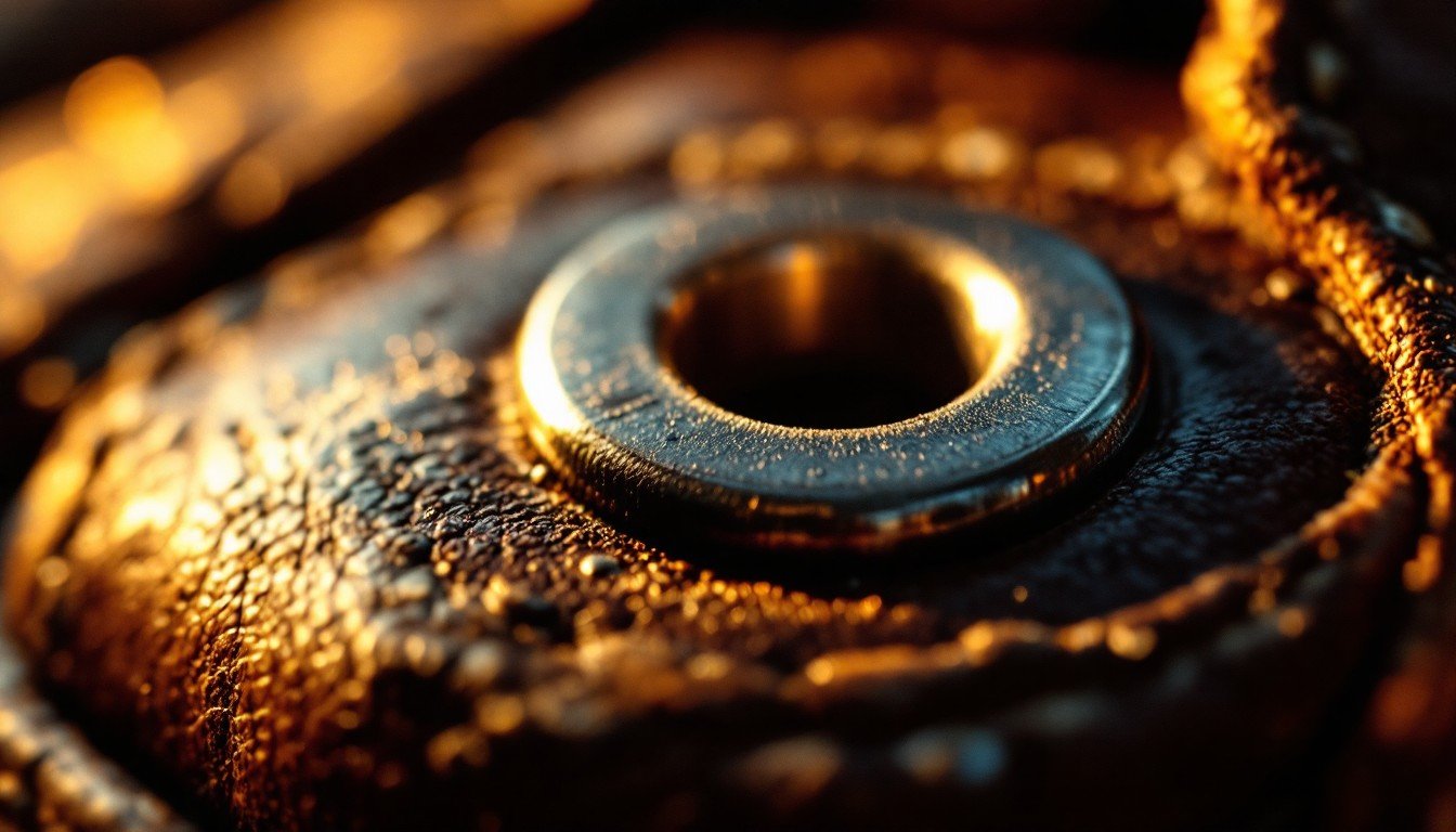
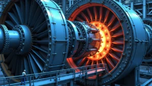
In the demanding world of turbine engineering, where massive rotating shafts spin at thousands of RPM while carrying enormous loads, the level of understanding how journal bearings work can make or break an entire system. At the heart of virtually every industrial turbine—from steam and gas turbines powering electrical grids to hydroelectric generators harnessing river flows—lies a critical component that most engineers take for granted: the journal bearing.
Unlike the familiar ball bearings found in everyday machinery, journal bearings represent a fundamentally different approach to supporting rotating equipment. Massive rotors weighing several tons must spin with microscopic precision, often for years without interruption. The combination of extreme centrifugal forces, thermal expansion from operating temperatures exceeding 500°C, and the relentless vibrations inherent in high-speed rotation demands a bearing solution that goes far beyond what ball or roller bearings can deliver.
This is where journal bearings shine. These seemingly simple cylindrical components create a thin film of pressurized lubricant that completely separates the rotating shaft from the bearing surface—a phenomenon that allows them to operate virtually wear-free for decades. Their ability to accommodate misalignment, dampen vibrations, and maintain stable operation under varying load conditions makes them indispensable for turbine applications where reliability isn’t just important—it’s absolutely critical.
This guide explores the theory, different types of journal bearings and their applications, and operating principles that make journal bearings the backbone of modern turbomachinery.
What Exactly is a Journal Bearing?
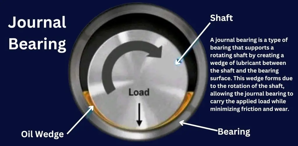
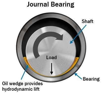
A journal bearing is a type of plain bearing designed to support a rotating shaft by allowing it to run directly within a smooth, cylindrical surface. When the shaft rotates, a thin layer of oil (called the oil wedge) forms between the shaft (called the journal) and the cylindrical surface (called the bearing surface). This oil film prevents direct metal-to-metal contact, significantly reducing friction, minimizing wear, and ensuring smooth, reliable rotation. These journal bearing working principles apply across all turbine applications.
To understand how journal bearings work, we must examine the fundamental difference of load transfer mechanism between rolling element bearing and journal bearing. Rolling element bearings distribute load through discrete contact points between the rolling elements and raceways, creating stress concentrations that limit their load capacity and operating speed. Journal bearings, conversely, distribute loads across a continuous curved surface through a pressurized oil film, eliminating stress concentrations and enabling them to handle much higher loads at greater speeds.
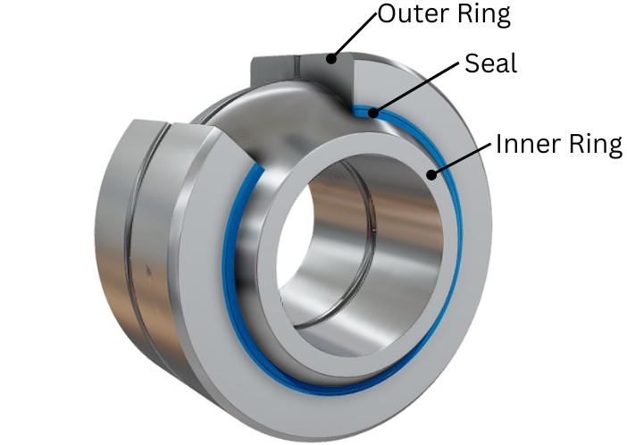
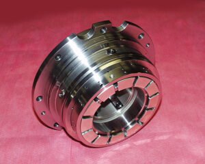
Key Components of a Journal Bearing System
- The Journal: This is the cylindrical section of the rotating shaft that sits within the bearing.
- Bearing Shell (or Bush): The stationary cylindrical housing that surrounds the journal, typically made from materials like white metal (Babbitt), bronze, or modern polymer composites. The shell’s inner surface is carefully profiled to optimize oil film formation and pressure distribution.
- Oil Film: The critical lubricant layer, typically just 0.001 to 0.003 inches thick, that completely separates the journal from the bearing shell during operation. This microscopic film carries the entire load of the rotating assembly.
- Housing: The structural component that holds the bearing shell in place and provides oil supply and drainage passages. The housing must be rigid enough to maintain precise clearances while accommodating thermal expansion.
Where Are Journal Bearings Located in a Turbine?
Within a turbine assembly, journal bearings are strategically positioned at critical support points along the rotor shaft. In a typical steam turbine, you’ll find journal bearings at the generator end and turbine end of the main shaft, with additional bearings supporting intermediate shaft sections in multi-stage units. Gas turbines commonly employ journal bearings to support both the compressor and turbine sections of the rotor assembly.
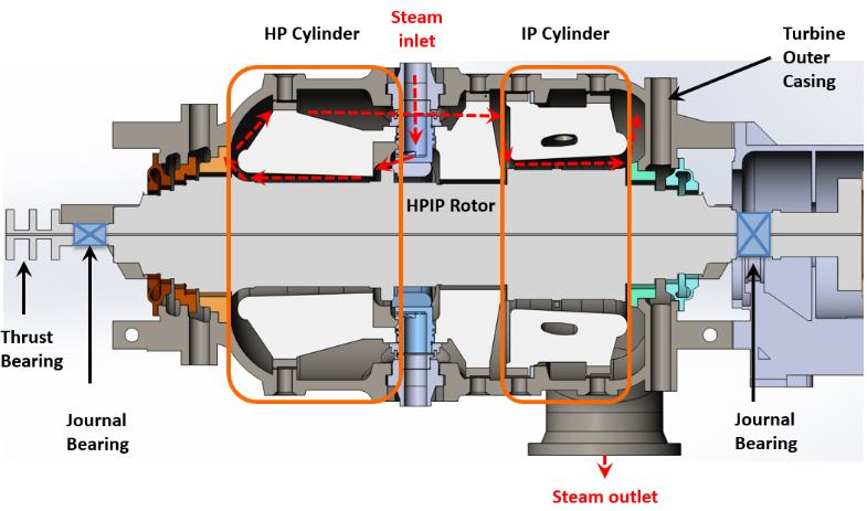
These bearings are housed within bearing pedestals—massive structural foundations that transfer the enormous rotating loads into the turbine’s foundation. The precise positioning of these bearings is crucial, as they must maintain perfect shaft alignment while accommodating the thermal growth that occurs as the turbine reaches operating temperature.
The Science Behind Journal Bearings: Hydrodynamic Lubrication
The remarkable ability of journal bearings to support massive loads without wear stems from a fascinating fluid mechanics phenomenon called hydrodynamic lubrication. This process transforms ordinary lubricating oil into a high-pressure cushion capable of lifting tons of rotating machinery with nothing more than the shaft’s own rotation.
1. Understanding Hydrodynamic Lubrication
Hydrodynamic lubrication occurs when a moving surface drags a viscous fluid into a converging gap, creating pressure sufficient to separate the surfaces completely. In journal bearings, this principle manifests as the rotating shaft pulls oil into the narrowing clearance space, generating pressures that can reach thousands of pounds per square inch—more than enough to support even the heaviest turbine rotors.
The key to this process lies in the viscous nature of the lubricant. As the journal rotates, it adheres to the oil molecules through viscous forces, dragging them along the bearing surface. When this oil encounters the converging geometry between the journal and bearing shell, it cannot escape quickly enough, creating a pressure buildup that pushes the shaft away from the bearing surface.
2. Formation of the Oil Wedge
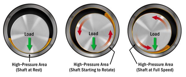
The creation of the supporting oil film begins with shaft rotation and the formation of what engineers call the “oil wedge.” As the journal starts rotating, it initially contacts the bearing shell at the bottom due to gravity. However, as rotational speed increases, the journal begins to drag oil around its circumference.
The critical moment occurs when the oil being dragged by the journal encounters the narrowing gap between the journal and bearing shell. This converging geometry forces the oil to compress, and because liquids resist compression, pressure builds rapidly. The highest pressures develop in the narrowest section of the oil wedge, typically occurring at an angle of 20-30 degrees from the point of minimum clearance. This process demonstrates exactly how journal bearings work at the molecular level.
3. Shaft Lift-Off and Oil Film Pressure Distribution
As the oil pressure increases with rotational speed, it eventually overcomes the gravitational and applied loads on the shaft, causing “lift-off”—the moment when the journal rises and becomes completely separated from the bearing surface. This transition from boundary lubrication to full hydrodynamic lubrication is one of the most critical phases in bearing operation.
The pressure distribution within the oil film is not uniform. It follows a characteristic pattern with peak pressure occurring in the load-carrying region of the bearing, gradually decreasing toward the oil inlet and outlet areas. This pressure profile creates a stable equilibrium position for the journal, automatically balancing the applied loads with the hydrodynamic forces.
These fundamental journal bearing working principles enable decades of reliable operation across the globe.
4. The Critical Triad: Speed, Viscosity, and Clearance
Three fundamental parameters govern hydrodynamic lubrication effectiveness: rotational speed, oil viscosity, and bearing clearance. These variables are interrelated through the Reynolds equation, which describes fluid flow in thin films.
- Speed directly impacts oil film pressure—higher rotational speeds generate greater pressure by dragging more oil into the converging wedge. This is why journal bearings perform better at higher speeds, unlike rolling element bearings that face increased stress with speed.
- Viscosity determines the oil’s ability to generate pressure when sheared. Higher viscosity oils create thicker films and higher pressures but also generate more friction and heat. The challenge lies in selecting a viscosity that provides adequate film thickness while maintaining acceptable operating temperatures.
- Clearance affects both oil film thickness and pressure generation. Tighter clearances create higher pressures but thinner films, while larger clearances reduce pressure but increase film thickness. The optimal clearance represents a carefully calculated compromise between load capacity and film thickness safety margins.
5. Self-Centering Behavior: The Beauty of Hydrodynamic Stability
Perhaps the most elegant characteristic of properly designed journal bearings is their inherent self-centering behavior. When external forces attempt to displace the journal from its equilibrium position, the hydrodynamic pressure distribution automatically adjusts to counteract the disturbance.
If a transient load pushes the journal toward one side of the bearing, the oil film thickness decreases on that side while increasing on the opposite side. The reduced clearance on the loaded side generates higher pressures, while the increased clearance on the unloaded side produces lower pressures. This pressure differential creates a restoring force that pushes the journal back toward its stable operating position.

This self-stabilizing characteristic is crucial in turbine applications where shaft dynamics, thermal effects, and varying operating conditions constantly try to disturb the rotor position. The bearing’s ability to automatically adjust its support characteristics ensures stable operation across a wide range of operating conditions without external control systems.
Types of Journal Bearings in Turbines
While all journal bearings operate on the same hydrodynamic principles, turbine applications demand specialized designs optimized for specific operating conditions and performance requirements. Each bearing type offers unique advantages that make it suitable for particular locations within the turbine assembly. Understanding the various types of journal bearings is crucial for proper selection.
I. Sleeve Bearings (Plain Cylindrical Bearings)
Sleeve bearings represent the simplest form of journal bearing—a smooth cylindrical shell that surrounds the journal with uniform clearance. Despite their apparent simplicity, these bearings form the backbone of many turbine applications due to their reliability, ease of manufacture, and excellent load-carrying capacity.
The uniform geometry of sleeve bearings creates a predictable pressure distribution and stable operation under steady loads. However, their simplicity can become a limitation under dynamic loading conditions, where their fixed geometry cannot adapt to changing operational demands. Modern sleeve bearings often incorporate features like axial grooves for oil distribution and pressure relief slots to optimize performance.
II. Tilting Pad Bearings
Tilting pad bearings revolutionized turbine bearing technology by introducing adaptability into the bearing geometry. Instead of a fixed cylindrical shell, these bearings consist of multiple independent pads (typically 4-6) that can pivot or “tilt” to optimize their alignment with the journal under different loading conditions.
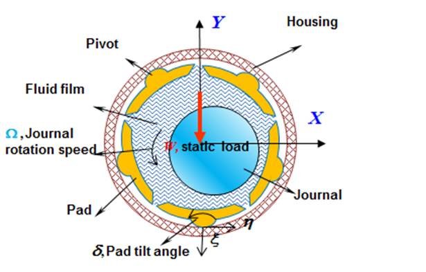
Each pad operates as an individual bearing, automatically adjusting its angle to create the optimal oil wedge and clearance for the local loading conditions particularly effective under varying load conditions. This self-aligning capability provides superior stability, reduced sensitivity to shaft misalignment, and excellent dynamic characteristics that resist oil whirl and other instability phenomena. The segmented design also provides better heat dissipation since oil can flow freely between pads, carrying away friction-generated heat more effectively than in sleeve bearings.
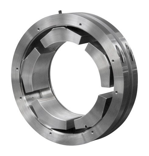
This represents one of the most common types of journal bearings in modern turbine applications.
>>> Checkout tilting pad bearing design principles.
III. Pressure Dam Bearings
Pressure dam bearings incorporate strategically placed raised sections or “dams” on the bearing surface to modify oil flow patterns and pressure distribution. These dams interrupt the circumferential oil flow, creating localized high-pressure zones that enhance load capacity and stability characteristics.
The dams act as pressure intensifiers, forcing oil to build up higher pressures in specific regions of the bearing. This controlled pressure manipulation allows engineers to tailor the bearing’s load distribution and stiffness characteristics to match specific application requirements. Pressure dam bearings are particularly effective in applications where additional stability margin is needed or where space constraints limit bearing size.
>>> Checkout API bearing design specifications here.
IV. Offset Bearings (Lemon Bore Bearings)
Offset bearings feature a deliberately non-concentric bore geometry where the bearing center is offset from the housing center, creating a “lemon-shaped” clearance pattern. This geometric modification pre-loads the bearing, establishing a convergent oil wedge even under light load conditions.
The offset geometry ensures that adequate oil film pressure develops at all operating speeds, including during startup and shutdown when conventional bearings might operate in boundary lubrication. This characteristic makes offset bearings particularly valuable in applications with frequent starts and stops or where minimum film thickness must be maintained under varying load conditions.
The pre-loaded design also provides enhanced damping characteristics, helping to suppress shaft vibrations and improve overall system stability. However, the asymmetric geometry increases complexity in manufacturing and requires more precise installation procedures.
Application Guidelines for Journal Bearings in Turbines
Understanding how journal bearings work across different turbine types requires a systematic approach to bearing selection. The choice between various types of journal bearings depends on multiple interrelated factors including operating speed, load characteristics, thermal environment, and maintenance requirements.
Primary Selection Criteria
Operating Speed Considerations
- Low Speed (< 1800 RPM): Sleeve bearings provide adequate performance with minimal complexity
- Medium Speed (1800-6000 RPM): Multiple bearing types suitable, selection based on load stability
- High Speed (> 6000 RPM): Tilting pad bearings preferred for dynamic stability
- Ultra-High Speed (> 15000 RPM): Specialized tilting pad designs with enhanced cooling
Load Profile Analysis
- Steady, unidirectional loads: Sleeve bearings excel with predictable pressure distribution
- Variable loads: Tilting pad bearings adapt to changing conditions automatically
- High thrust loads: Pressure dam bearings provide enhanced axial load capability
- Shock loads: Offset bearings maintain film integrity during transient conditions
Thermal Environment Factors
- Moderate temperatures (< 200°F): Standard Babbitt materials suitable for all bearing types
- High temperatures (200-400°F): Bronze-backed bearings or enhanced cooling required
- Extreme temperatures (> 400°F): Specialized materials and active cooling systems mandatory
Steam Turbine Applications
Large Utility Steam Turbines (500-1500 MW)
Generator End Bearings Selecting between different types of journal bearings for generator applications prioritizes load capacity and operational stability. Large, slow-speed steam turbines (1800-3600 RPM) typically employ sleeve bearings at the generator end where loads are steady and predictable. The massive rotor weight (often 100-300 tons) requires maximum load-carrying capacity, making the continuous support surface of sleeve bearings ideal.
Design specifications typically include:
- Bearing diameters: 24-48 inches
- Unit loading: 150-300 psi
- Clearance ratios: 0.0015-0.0025
- Babbitt thickness: 0.125-0.250 inches
Turbine End Bearings The turbine end experiences more complex loading due to steam forces and thermal effects, often utilizing tilting pad bearings for their superior adaptability. Axial steam thrust, thermal growth effects, and varying steam conditions create dynamic loading that benefits from the self-aligning characteristics of tilting pad designs.
Critical considerations include:
- Thermal shock resistance during startup
- Accommodation of differential thermal expansion
- Steam seal integration requirements
- Emergency shutdown capability
Intermediate Pressure and Reheat Sections
High-pressure steam turbines frequently use pressure dam bearings at intermediate shaft locations where additional stability is required to handle the complex loading from multiple turbine stages. The ability to customize pressure distribution makes these bearings ideal for managing the varying radial and axial forces present in multi-stage designs.
Typical applications:
- HP-IP coupling bearings
- Intermediate shaft supports in tandem compound units
- Crossover section supports
Industrial Steam Turbines (1-100 MW)
Smaller industrial steam turbines offer more flexibility in bearing selection due to reduced absolute loads and operating constraints. Journal bearing working principles remain consistent, but cost considerations often favor simpler designs.
Common configurations:
- Single-stage units: Sleeve bearings at both ends
- Multi-stage units: Sleeve bearing at generator end, tilting pad at turbine end
- Extraction turbines: Pressure dam bearings for variable loading conditions
Gas Turbine Applications
Heavy-Duty Gas Turbines (100-500 MW)
Gas turbines present more challenging bearing requirements due to higher operating speeds (often exceeding 10,000 RPM) and more severe thermal conditions. Understanding how journal bearings work under these extreme conditions is crucial for reliable operation.
Compressor End Requirements The compressor end typically uses tilting pad bearings to handle the high axial thrust loads and provide the stability needed for high-speed operation. Compressor discharge pressures create significant axial forces that must be managed through both thrust and journal bearing systems.
Critical design features:
- Five or six-pad configurations for maximum stability
- Directed lubrication for enhanced cooling
- Anti-rotation pins to prevent pad movement
- Instrumentation for continuous monitoring
Turbine End Challenges Similarly, the turbine end employs tilting pad designs to manage the extreme thermal conditions and dynamic loading from the hot gas expansion process. Temperatures can exceed 1000°F near the bearing housing, requiring sophisticated cooling systems.
Thermal management strategies:
- Oil mist cooling systems
- Insulated bearing housings
- Temperature-controlled oil supply
- Emergency backup cooling
Aeroderivative Gas Turbines
Aeroderivative units, derived from aircraft engines, operate at even higher speeds (10,000-20,000 RPM) with different bearing requirements. These applications often use specialized bearing designs adapted from aerospace technology.
Unique characteristics:
- Ultra-high speed capability
- Lightweight construction requirements
- Rapid startup/shutdown cycles
- Aerospace-grade materials and manufacturing
Industrial Gas Turbines (1-50 MW)
Smaller industrial gas turbines may use offset bearings where space constraints limit bearing size but startup/shutdown durability is critical. The pre-loaded design ensures adequate lubrication during the frequent cycling common in peaking power applications.
Selection factors:
- Package size limitations
- Maintenance accessibility
- Operating cycle frequency
- Cost optimization requirements
Specialized Applications
Hydroelectric Turbines
Hydroelectric turbines, with their unique combination of low speed and extremely high loads, typically employ large sleeve bearings with specialized cooling systems. The steady-state nature of hydro operation makes the simplicity and high load capacity of sleeve bearings ideal for these applications.
Hydro-specific requirements:
- Massive load capacity (1000+ psi unit loading)
- Water cooling systems
- Sealing against water ingress
- Long-term reliability (40-50 year design life)
Types of journal bearings used:
- Francis turbines: Large sleeve bearings with oil circulation cooling
- Kaplan turbines: Sleeve bearings with water cooling jackets
- Pelton wheels: Sleeve bearings with enhanced oil supply systems
Combined-Cycle Plants
Combined-cycle plants often use hybrid approaches, with different bearing types at various locations depending on the specific requirements of each shaft position. The flexibility to mix bearing types allows engineers to optimize performance while managing costs and maintenance requirements.
System integration considerations:
- Common oil systems serving multiple turbines
- Coordinated control and monitoring
- Maintenance scheduling optimization
- Spare parts standardization
Marine and Offshore Applications
Marine turbines face unique challenges including vibration from wave action, corrosive environments, and limited maintenance access. Journal bearing working principles must accommodate these harsh conditions.
Marine-specific adaptations:
- Enhanced corrosion resistance
- Vibration-tolerant designs
- Simplified maintenance procedures
- Redundant monitoring systems
Bearing Selection Decision Matrix
| Application Requirements | Sleeve Bearing | Tilting Pad | Pressure Dam | Offset Bearing |
|---|---|---|---|---|
| Speed Range | ||||
| Low (< 1800 RPM) | Excellent | Overdesigned | Overdesigned | Good |
| Medium (1800-6000 RPM) | Good | Excellent | Good | Good |
| High (> 6000 RPM) | Poor | Excellent | Limited | Poor |
| Load Characteristics | ||||
| Steady, Constant | Excellent | Good | Good | Good |
| Variable Loads | Limited | Excellent | Good | Good |
| Shock Loads | Poor | Good | Limited | Excellent |
| High Thrust Loads | Limited | Good | Excellent | Limited |
| Stability Requirements | ||||
| Standard Applications | Excellent | Good | Good | Good |
| High-Performance | Limited | Excellent | Good | Limited |
| Critical Stability | Poor | Excellent | Limited | Poor |
| Economic Factors | ||||
| Low Initial Cost | Excellent | High | Medium | Medium |
| Low Maintenance | Excellent | Medium | Good | Good |
| Environmental | ||||
| High Temperature | Limited | Excellent | Good | Limited |
| Contaminated Conditions | Good | Limited | Limited | Good |
| Space Constraints | Good | Limited | Good | Excellent |
Mastering the Fundamentals: Your Foundation for Practical Application
Understanding journal bearing types and hydrodynamic principles provides the essential foundation every turbine engineer needs. You’ve now learned how journal bearings work through hydrodynamic principles, how microscopic oil films can support tons of rotating equipment, major types of journal bearings, why different bearing types excel in specific applications, and the physics that makes decades of reliable operation possible.
But theory alone doesn’t solve real-world turbine challenges. The next crucial step is applying these fundamentals to practical engineering decisions—selecting proper design parameters, preventing common failures, and troubleshooting problems when they arise.
In our companion guide, “Journal Bearing Design and Troubleshooting for Turbines: Practical Engineering Guide” we’ll bridge the gap between theory and practice. You’ll discover how to translate these principles into robust bearing designs, recognize early warning signs of problems, and implement proven troubleshooting strategies that prevent costly turbine failures.
Ready to move from understanding how journal bearings work to making them work reliably in your applications? Continue with the practical implementation guide to complete your journal bearing expertise.
~Rotormind


3 Comments
Comments are closed.