Nitrogen Generation Systems in Power Plants: Complete Guide to Membrane Technology, Operations & Maintenance
Introduction: Why Every Modern Power Plant Needs Reliable Nitrogen
When I started my career in power generation, most plants relied on delivered nitrogen cylinders or bulk tanks. We’d constantly worry about running out during critical operations, and the costs kept climbing. Today, I always recommend on-site nitrogen generation systems to young engineers designing new facilities or upgrading existing ones.
“Why is nitrogen so crucial in power plants? “
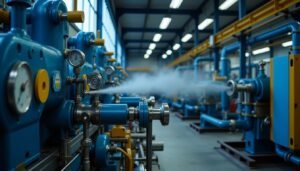
Think of nitrogen as the “safety blanket” of power generation. It’s an inert gas that prevents combustion, protects equipment during maintenance, and ensures safe operations during startup and shutdown procedures. Without reliable nitrogen supply, you’re essentially operating without a safety net.
The economics are compelling too. A typical 500 MW coal plant might spend $200,000-300,000 annually on delivered nitrogen. An on-site generation system pays for itself in 2-3 years while providing 24/7 reliability. I’ve never met a plant manager who regretted installing one.
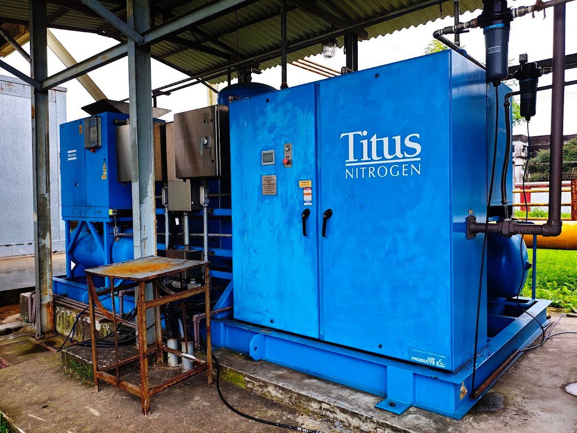
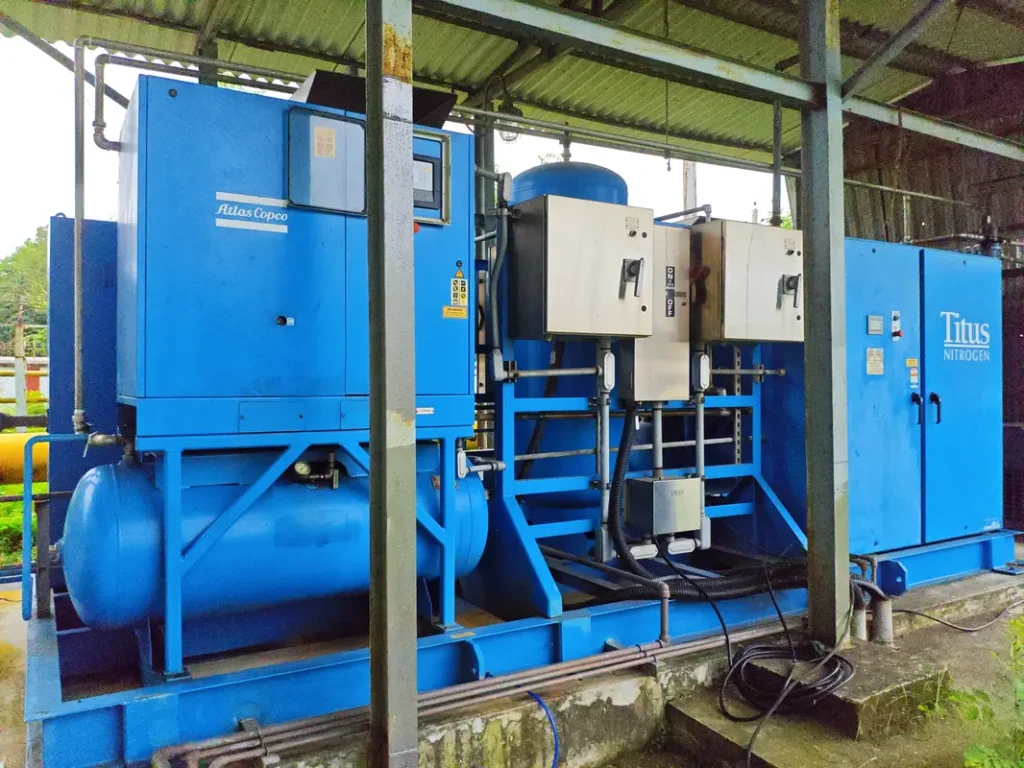
Modern membrane-based nitrogen plants have revolutionized how we approach nitrogen supply. These systems are so reliable and low-maintenance that many operators forget they’re even there – which is exactly how it should be. Let me explain how they work and why they’ve become the industry standard.
Understanding the Fundamentals: It’s All About Separation
Before diving into the technology, let’s establish the basics. The air we breathe is roughly 78% nitrogen, 21% oxygen, and 1% other gases. The key insight here is that we’re not “making” nitrogen – we’re simply separating it from the other components in air.
This is where many young engineers get confused. They think nitrogen generation is some complex chemical process. In reality, it’s purely physical separation based on molecular properties. No chemical reactions, no exotic materials – just smart engineering that exploits natural molecular behavior.
Nitrogen Separation Technologies
- Cryogenic Distillation: The old-school method using extreme cold to liquefy and separate gases. Think of it as the “brute force” approach. It works great for very large volumes but is overkill for most power plant applications.
- Pressure Swing Adsorption (PSA): Uses special materials that preferentially absorb oxygen under pressure. When pressure is released, oxygen is expelled, leaving nitrogen behind. It’s like a molecular sponge that’s very picky about what it absorbs.
- Membrane Separation: The modern favorite that we’ll focus on. Uses special hollow fiber membranes that allow oxygen to pass through faster than nitrogen. It’s elegant, simple, and perfectly suited for power plant applications.
I always tell my team: “Choose the technology that matches your needs, not the one that sounds most impressive.” For power plants, membrane technology wins almost every time.
Nitrogen Separation Technologies Comparison Chart
| Criteria | Membrane Separation | Pressure Swing Adsorption (PSA) | Cryogenic Distillation |
|---|---|---|---|
| Technology Principle | Selective permeation through hollow fiber membranes | Alternating pressure cycles with molecular sieves | Liquefaction and fractional distillation |
| Typical Purity Range | 90-99.9% | 95-99.999% | 99.5-99.999% |
| Flow Rate Range | 10-5,000 SCFM | 50-50,000 SCFM | 1,000+ SCFM (large scale) |
| Capital Cost | Low ($100K-500K) | Medium ($200K-800K) | High ($1M-10M+) |
| Operating Cost | Low-Medium | Medium | High |
| Energy Consumption | 15-25 kW per 100 SCFM | 20-35 kW per 100 SCFM | 25-45 kW per 100 SCFM |
| Startup Time | Immediate (< 5 minutes) | Fast (15-30 minutes) | Slow (2-8 hours) |
| Maintenance Level | Very Low | Medium | High |
| Complexity | Simple | Medium | Complex |
| Moving Parts | Minimal (compressor only) | Multiple valves, controls | Many rotating equipment |
| Footprint | Compact | Medium | Large |
| Reliability | Excellent (>98%) | Good (95-97%) | Good (95-97%) |
| Turndown Ratio | 10:1 | 3:1 | Limited |
| Product Recovery | 15-50% | 40-70% | 95%+ |
| Best Applications | Power plants, small-medium industrial | Medium-large industrial, laboratories | Large chemical plants, air separation |
Membrane Technology: The Molecular Highway System
Now, let’s dive into the heart of modern nitrogen generation – membrane technology. I like to explain this using the analogy of a highway system with different speed limits for different types of vehicles.
How Hollow Fiber Membranes Work
Imagine thousands of tiny hollow tubes, each thinner than a human hair, bundled together like a fiber optic cable. These tubes are made from special polymer materials with microscopic pores. When compressed air flows through the inside of these tubes, something fascinating happens at the molecular level.
Different gas molecules have different permeation rates through the membrane wall. Oxygen, carbon dioxide, and water vapor are “fast” molecules – they zip through the membrane wall quickly. Nitrogen is a “slow” molecule – it prefers to stay inside the tube and continue its journey to the outlet.
The Separation Process
Here’s how it works in practice:
- Compressed air enters the membrane module
- “Fast” gases (O₂, CO₂, H₂O) permeate through the membrane wall
- These gases are collected as “permeate” or waste stream
- “Slow” nitrogen continues through the fiber and exits as product gas
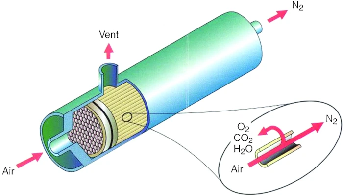
The beauty of this system is its simplicity. No moving parts in the separation process, no regeneration cycles, no complex controls. The driving force is simply the pressure differential across the membrane wall.
Key Components of a Membrane System
Let me walk you through the essential components you’ll find in every membrane nitrogen generator:
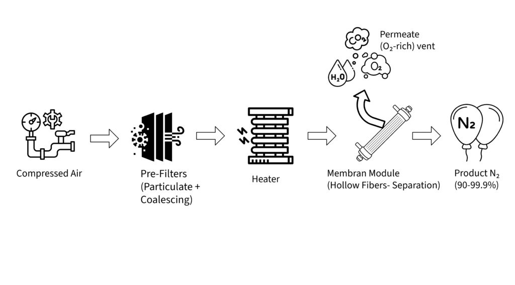
Compressed Air Supply: Typically requires 80-150 PSIG clean, dry air. I always size the compressor with 20% excess capacity – you’ll thank me later when demand unexpectedly increases.
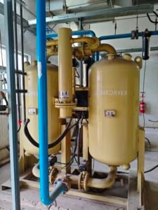
Pre-filtration System: This is where many systems fail if neglected. You need:
- Particulate filter (1.0 micron) to remove solid contaminants
- Coalescing filter (0.01 micron) to remove oil and water aerosols
- Automatic drain systems to remove collected liquids
Process Air Heater: Maintains optimal membrane temperature (typically 100-140°F). Temperature matters because it affects permeation rates and prevents condensation in the membranes.
Membrane Separator Modules: The heart of the system. Quality modules can last 10-15 years with proper air preparation.
Purity Control System: Usually consists of a metering valve and back pressure regulator working together to balance flow rate and purity.
Understanding the Purity vs. Flow Trade-off
This is crucial for young engineers to understand: you can’t have maximum purity and maximum flow simultaneously. It’s a fundamental trade-off that governs system design.
Want higher purity? You need to:
- Reduce the nitrogen flow rate
- Increase the permeate vent rate
- Accept higher operating costs
Need more flow? You’ll have to:
- Accept lower purity
- Optimize the permeate-to-product ratio
- Possibly add more membrane area
I always design systems with flexibility in mind. Better to have a system that can produce 95% purity at high flow rates and 99% purity at moderate flow rates than one that’s locked into a single operating point.
Power Plant Applications: Where Nitrogen Saves Lives and Equipment
After working a significant time in power generation, I’ve seen nitrogen prevent accidents and equipment failures. Let me share the critical applications where nitrogen systems prove their worth every single day.
Boiler Systems: The Primary Safety Application
This is where nitrogen generation systems pay for themselves in safety alone. During boiler startup and shutdown, we create potentially dangerous conditions where combustible gases can accumulate. Nitrogen purging eliminates these risks.
- Startup Procedures: Before lighting any burner, we purge the entire combustion system with nitrogen. This removes any residual combustible gases and creates an inert atmosphere.
- Shutdown Procedures: After taking a boiler offline, nitrogen purging prevents the formation of explosive mixtures as the system cools down. Hot surfaces can ignite residual hydrocarbons if oxygen is present.
- Mill Purging: Coal mills are particularly hazardous. The combination of pulverized coal dust and air creates explosion risks. Nitrogen inerting reduces oxygen concentration below combustible levels.
Turbine Applications: Protecting Million-Dollar Assets
Modern gas and steam turbines represent enormous investments. Nitrogen plays several critical roles in protecting these assets:
- Generator Cooling: Large generators often use hydrogen for cooling due to its excellent heat transfer properties. Nitrogen provides the inert barrier gas that prevents hydrogen-air mixing at seal points. One seal failure without nitrogen backup can destroy a generator worth millions.
- Turbine Preservation: During extended outages, nitrogen keeps moisture and corrosive gases away from precision turbine components. I always specify nitrogen blanketing for outages longer than 30 days.
Fuel System Safety
- Natural Gas Applications: Nitrogen provides safe purging for gas piping systems during maintenance. It also serves as a backup fuel for some low-NOx burner systems.
- Oil Systems: Heavy fuel oil tanks benefit from nitrogen blanketing to prevent oxidation and reduce fire risks. The nitrogen blanket also minimizes vapor losses.
Environmental System Support
- SCR Systems: Selective Catalytic Reduction systems use ammonia, which can be hazardous. Nitrogen provides safe dilution and purging capabilities.
- Mercury Control: Some mercury control systems require inert environments for optimal performance.
I always tell plant operators: “Nitrogen isn’t just another utility – it’s your insurance policy against catastrophic failures.”
System Design: Getting It Right From Day One
Here’s where experience really matters. I’ve seen too many nitrogen systems that were undersized, improperly configured, or installed without considering future needs. Let me share the key design principles that separate successful installations from problematic ones.
I. Capacity Sizing: The 1.5 Rule
Never, and I mean never, size a nitrogen system for exactly your calculated peak demand. Use what I call the “1.5 Rule” – size for 150% of your calculated peak demand. Here’s why:
- Demand calculations are often conservative
- Future plant modifications will increase nitrogen needs
- Membrane performance degrades slightly over time
- You want operational flexibility during peak demand periods
Real-World Example: For a 500 MW plant, if your calculations show 100 SCFM peak demand, design for 150 SCFM minimum capacity. Trust me on this – I’ve never heard a plant manager complain about having too much nitrogen capacity.
II. Storage Tank Strategy
Storage tanks serve two critical functions:
- Demand Smoothing: Handle short-term peak demands without oversizing the generator
- Emergency Reserve: Provide nitrogen during generator maintenance or failures
Size your storage for at least 30 minutes of peak demand, preferably 60 minutes. This gives operators time to respond to system issues without shutting down critical processes.
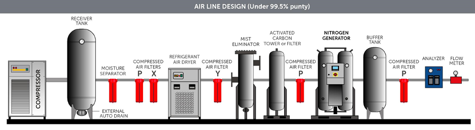
III. Air Supply: The Foundation of Success
The air compressor and treatment system is where many projects go wrong. Here are the non-negotiables:
Air Quality Requirements:
- Pressure dew point: -40°F or better
- Oil content: Less than 0.1 ppm
- Particulate: Less than 1.0 micron
- Pressure: 135 PSIG minimum (I prefer 150 PSIG for flexibility)
Compressor Selection: I always recommend oil-free compressors for nitrogen generation duty. Yes, they cost more upfront, but oil contamination will destroy membrane performance. The extra cost is insurance you’ll be glad you bought.
IV. Redundancy Considerations
For critical applications, design with N+1 redundancy. This means if you need one nitrogen generator, install two. If you need two, install three. The incremental cost is small compared to the consequences of losing nitrogen supply during critical operations.
V. Installation Requirements: Location, Location, Location
Ambient Conditions: Nitrogen generators prefer stable temperatures between 40-110°F. Avoid locations with extreme temperature swings or poor ventilation.
Permeate Gas Venting: This is a safety-critical design element. The oxygen-rich permeate gas must be vented at least 12 feet above grade, away from air intakes and ignition sources. I’ve seen installations where this was done incorrectly – it creates serious fire hazards.
Electrical Infrastructure: Plan for 480V 3-phase power with adequate capacity for heaters, controls, and potential future expansion. Include uninterruptible power supplies for critical control systems.
Safety First: Lessons Learned the Hard Way
In my career, I’ve investigated several nitrogen-related incidents. Most were preventable with proper understanding of the hazards and appropriate safety measures. Let me share the critical safety considerations that every power plant professional must understand.
The Invisible Killer: Asphyxiation Hazards
Nitrogen is colorless, odorless, and tasteless. You cannot detect it with your senses, which makes it extremely dangerous in confined spaces. A nitrogen leak in an enclosed area can create a deadly atmosphere without any warning signs.
The 19% Rule: Human life requires a minimum of 19% oxygen in the atmosphere. Normal air contains 21% oxygen, so there’s very little margin for error. A nitrogen leak that reduces oxygen to 16% will cause unconsciousness. Below 10% oxygen is rapidly fatal.
Confined Space Protocols: I mandate these procedures for any work in areas with nitrogen systems:
- Continuous oxygen monitoring with calibrated instruments
- Forced ventilation systems operating before entry
- Rescue procedures with proper breathing apparatus
- Never work alone – always use the buddy system
Real-World Example: I once investigated an incident where maintenance personnel entered a tank that had been nitrogen-blanketed. The oxygen monitor wasn’t working, and two workers were overcome. Fortunately, proper rescue procedures saved their lives, but it was a close call that changed our safety protocols forever.
Oxygen-Enriched Permeate: The Fire Hazard
The permeate stream from membrane nitrogen generators contains 25-40% oxygen – significantly higher than normal air. This creates serious fire and explosion risks if not handled properly.
Material Compatibility: Never use PVC piping for permeate gas systems. PVC becomes highly flammable in oxygen-enriched environments. Use only:
- Stainless steel (304 or 316)
- Carbon steel
- Specialty oxygen-compatible materials
Proper Venting Requirements:
- Minimum 12 feet above grade level
- Away from air intakes, windows, and doors
- Away from ignition sources (electrical equipment, hot surfaces)
- Design to prevent water accumulation and freezing
Electrical Safety: More Than Just Lockout/Tagout
Nitrogen systems include heaters, compressors, and control systems that require special electrical safety considerations:
Grounding Requirements: Proper grounding is critical for both safety and system performance. Poor grounding can cause control system malfunctions and create shock hazards.
Hazardous Area Classification: While nitrogen isn’t flammable, the permeate gas creates oxygen-enriched environments that may require special electrical equipment ratings.
Maintenance Safety Protocols
Depressurization Procedures: Always fully depressurize systems before opening any pressure-containing component. Nitrogen systems operate at substantial pressures (80-150 PSIG) that can cause serious injuries.
Filter Element Replacement: This is the most common maintenance task and where most injuries occur. Always:
- Isolate the filter from system pressure
- Verify zero pressure with gauges and manual venting
- Use proper tools to avoid over-tightening
- Test for leaks before returning to service
Always remember: nitrogen might be inert, but the systems that produce it are not. Treat every component with respect.
>>> Checkout here for more safety regulations: Occupational Safety and Health Administration (OSHA) – Industrial gas safety regulations
Operation and Control: The Modern Approach
Today’s nitrogen generation systems are marvels of automation, but understanding their operation is crucial for reliable performance. Let me walk you through the control philosophy and operational considerations that separate excellent plants from average ones.
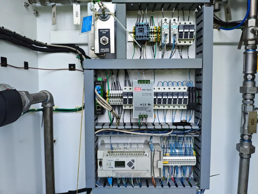
PLC-Based Control Systems: Your Digital Assistant
Modern nitrogen plants use sophisticated Programmable Logic Controllers (PLCs) that make operation almost foolproof. But “almost” is the key word – you still need to understand what’s happening behind the scenes.
The Control Triangle: Every nitrogen system controls three primary variables:
- Flow Rate: How much nitrogen you’re producing
- Purity: The oxygen content of the product gas
- Pressure: The delivery pressure to your plant systems
These three variables are interconnected. Change one, and the others respond. The PLC constantly balances these parameters to meet your setpoints.
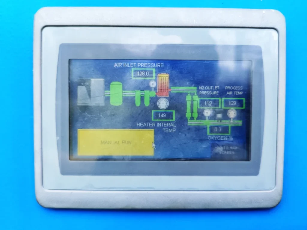
Human Machine Interface (HMI): Your Window Into the System
The touchscreen HMI is your primary interface with the nitrogen plant. Here’s what you should monitor regularly:
Key Process Parameters:
- Process Air Temperature: Should be 100-140°F for optimal performance
- Process Air Pressure: Monitor for drops that indicate filter problems
- Oxygen Content: Your primary quality indicator
- Nitrogen Flow Rate: Track against demand patterns
- Filter Differential Pressures: Early warning of maintenance needs
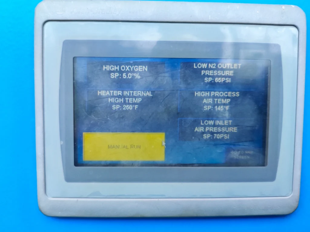
Alarm Management: Modern systems provide multiple alarm levels:
- Advisory: Notifications that don’t require immediate action
- Warning: Conditions that need attention within hours
- Critical: Immediate action required to prevent system shutdown
Redundant System Operation: Seamless Backup
Most power plants install redundant nitrogen generators for reliability. The control system manages automatic switchover based on:
Scheduled Switchover: Alternates between units on a time basis (typically weekly or monthly) to ensure both systems stay exercised.
Emergency Switchover: Automatic change to backup unit when:
- Primary unit oxygen content exceeds setpoint
- Primary compressor fails
- Critical alarm conditions occur
Performance Optimization Strategies
Flow Rate Management: Don’t just set it and forget it. Monitor nitrogen demand patterns and adjust production accordingly:
- Base Load: Continuous background demand for seal gas, blanketing
- Peak Demand: Short-term high usage for purging operations
- Seasonal Variations: Higher demand during maintenance outages
Purity Optimization: Match your nitrogen purity to application requirements:
- Boiler Purging: 95% purity is often sufficient
- Generator Seal Gas: May require 99%+ purity
- Equipment Preservation: 98% purity typically adequate
Energy Efficiency Considerations
The air compressor typically consumes 80-90% of the total system energy. Optimization strategies include:
Variable Speed Drives: Match compressor output to demand rather than running at constant speed with blow-off control.
Pressure Optimization: Don’t run higher pressure than necessary. Every 2 PSI reduction saves approximately 1% energy consumption.
Heat Recovery: Some installations recover waste heat from air compressor cooling for building heating or other processes.
Maintenance: The Key to Long-Term Success
Here’s where I see the biggest differences between well-run plants and those with constant problems. Nitrogen generators are relatively low-maintenance, but the maintenance they do require is absolutely critical. Skip it, and you’ll pay dearly in performance, reliability, and safety.
The Sacred Schedule: Non-Negotiable Maintenance Tasks
I call certain maintenance tasks “sacred” because they cannot be deferred without risking system integrity. Here’s your bible:
Weekly Tasks (15 minutes):
- Visual Filter Inspection: Check differential pressure gauges on all filters
- System Walkdown: Look for leaks, unusual noises, or visible problems
- Performance Check: Verify oxygen content and flow rates are normal
Monthly Tasks (2 hours):
- Comprehensive Leak Survey: Use soap solution or electronic leak detector
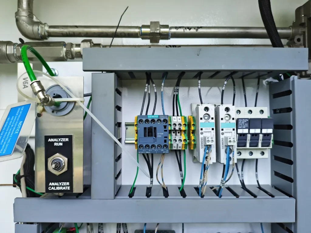
- Oxygen Analyzer Calibration: Critical for safety and product quality
- Auto Drain Function Test: Verify all automatic drains are working
- Control System Backup: Download and archive control system parameters
Semi-Annual Tasks (8 hours) – The Big One:
- Filter Element Replacement: This is absolutely critical and warranty-dependent
- Valve Exercising: Operate all manual and automatic valves through full range
- Heater Element Inspection: Check for scaling or degradation
- Instrumentation Calibration: Verify all pressure, temperature, and flow instruments
Annual Tasks (16 hours):
- Membrane Performance Test: Document capacity and efficiency trends
- Electrical System Inspection: Check connections, insulation, and protection devices
- Safety System Testing: Verify all alarms and shutdown functions
- Complete System Documentation Update: Record any changes or modifications
Filter Maintenance: Where Most Problems Start
I cannot overemphasize this point: Filter maintenance is the foundation of nitrogen generator reliability. Here’s what you need to know:
Why Filters Matter: The membrane modules are the most expensive component in your nitrogen plant. They’re also the most sensitive to contamination. Proper filtration extends membrane life from 5 years to 15+ years.
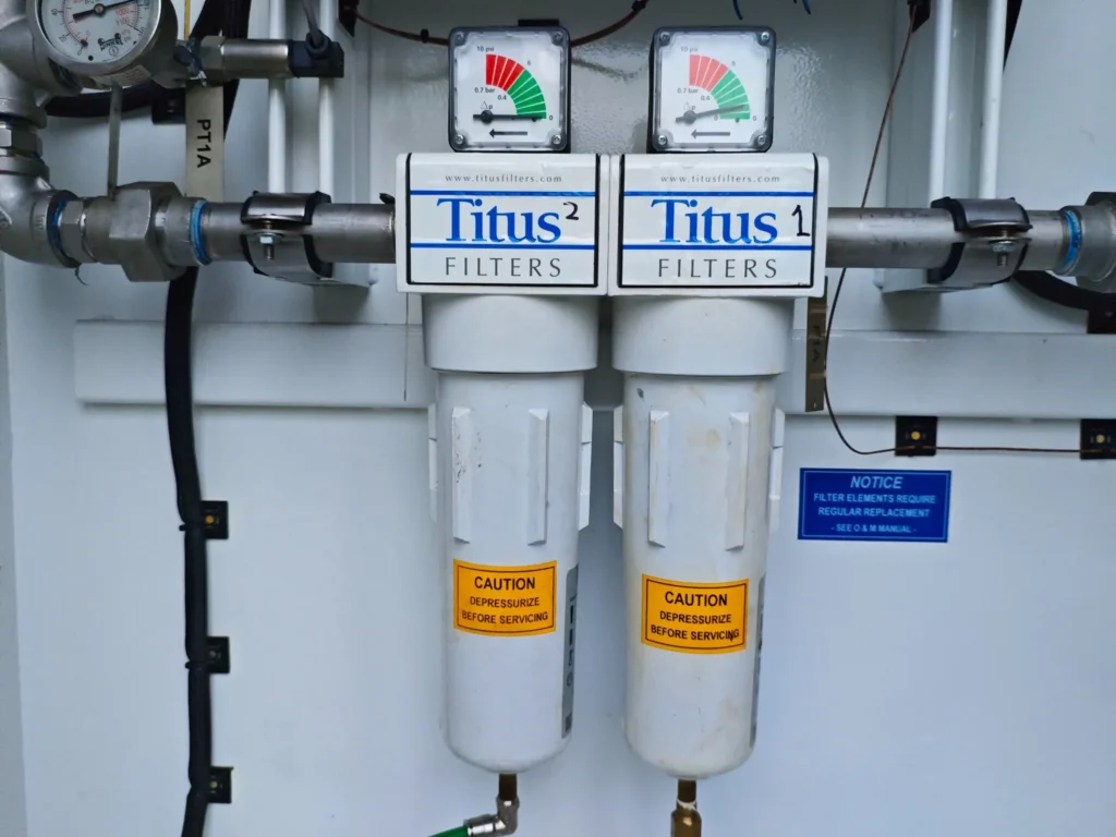
The 6-Month Rule: Replace filter elements every 6 months, regardless of differential pressure readings. This isn’t just best practice – it’s typically required to maintain your warranty.
Filter Replacement Procedure:
- Isolate and depressurize the filter housing
- Remove the bowl using proper tools (never use pipe wrenches!)
- Remove old element and inspect for unusual contamination
- Install new element with proper orientation
- Reassemble with new O-rings if required
- Pressure test and check for leaks
Cost vs. Value: Filter elements cost $200-500 each. Membrane module replacement costs $20,000-50,000. The math is pretty simple.
Oxygen Sensor Management: Your Quality Assurance
Calibration Schedule: Monthly calibration is mandatory. Use certified calibration gas (typically 20.9% oxygen in nitrogen) and follow manufacturer procedures exactly.
Replacement Cycle: Oxygen sensors have finite lives – typically 18-24 months. Don’t wait for failure; replace on schedule.
Sensor Types: Most systems use electrochemical sensors that consume oxygen to generate a signal. They gradually lose sensitivity and accuracy over time.
Predictive Maintenance: Working Smarter
Performance Trending: Track these key parameters over time:
- Nitrogen production rate at standard conditions
- Power consumption per SCFM produced
- Membrane differential pressure
- System efficiency (product gas/feed air ratio)
Warning Signs: These trends indicate developing problems:
- Gradual increase in oxygen content at constant flow
- Rising power consumption
- Increasing membrane pressure drop
- More frequent filter differential pressure buildup
Spare Parts Strategy: Be Prepared
Critical Spares (keep on-site):
- Complete set of filter elements
- Oxygen sensor
- Control system fuses and I/O modules
- Common valve diaphragms and seals
Long-Lead Items (order in advance):
- Membrane modules (6-12 month lead times)
- Major control system components
- Specialized instrumentation
Troubleshooting: When Things Go Wrong
Even the best-maintained systems occasionally have problems. Your response time and troubleshooting approach can mean the difference between a minor inconvenience and a major outage. Let me share the systematic approach I’ve developed over decades of solving nitrogen plant problems.
The SCOPE Method
I teach all my technicians to use the SCOPE troubleshooting method:
- Symptoms: What exactly is wrong?
- Conditions: When did it start? What changed?
- Observations: What do the instruments show?
- Possible causes: What could cause these symptoms?
- Elimination: Test each possibility systematically
High Oxygen Content: The Most Common Problem
This is the issue I see most frequently, and it usually has straightforward causes:
Filter-Related Causes (70% of cases):
- Plugged particulate filter reduces air flow, affecting separation efficiency
- Saturated coalescing filter allows liquid carryover into membranes
- Bypass around filters due to poor installation or maintenance
Diagnostic Steps:
- Check filter differential pressures immediately
- Verify automatic drains are functioning
- Look for liquid carryover downstream of filters
- Check filter element condition and installation
Temperature-Related Causes (20% of cases):
- Process air temperature too low affects membrane permeation rates
- Heater element failure or control problems
- Inadequate insulation causing heat loss
Quick Test: Temporarily increase temperature setpoint by 10°F and observe oxygen content. If it improves, you’ve found your problem area.
Flow-Related Causes (10% of cases):
- Nitrogen demand exceeding system capacity
- Improper purity valve settings
- Back pressure regulator problems
Low Nitrogen Flow: Capacity Problems
When your nitrogen plant can’t keep up with demand, work through these possibilities:
Air Supply Issues:
- Compressor capacity or pressure problems
- Plugged inlet filters or piping restrictions
- Compressor control issues
Diagnostic Approach: Check air supply pressure and flow first. If supply air is adequate, the problem is in the nitrogen generator itself.
System Configuration Problems:
- Purity valve set too restrictively
- Back pressure regulator malfunction
- Excessive system pressure drop
Membrane Degradation:
- Age-related performance decline
- Contamination damage
- Physical damage from pressure spikes
Process Temperature Issues: The Goldilocks Problem
Temperature control is critical – too hot, too cold, or unstable temperatures all cause problems.
High Temperature Problems:
- Heater control malfunction (most common)
- Inadequate air flow across heater elements
- Thermocouple failure giving false readings
Immediate Actions:
- Verify air flow through the system
- Check heater amperage draw
- Calibrate temperature instruments
Low Temperature Problems:
- Heater element failure
- Control system malfunction
- Inadequate electrical supply
Temperature Instability:
- Usually indicates control system tuning problems
- May be caused by variable air supply conditions
- Sometimes related to ambient temperature swings
Quick Reference Troubleshooting Matrix
| Problem | Symptoms | Immediate Checks | Likely Causes | Action Steps | Prevention |
|---|---|---|---|---|---|
| High Oxygen Content | O₂ > setpoint, poor purity | Filter differential pressure, process temperature, flow rates | 1. Clogged filters 2. Low process temperature 3. Excessive flow demand 4. Membrane degradation | 1. Check/replace filters 2. Verify heater operation 3. Reduce N₂ flow rate 4. Contact vendor if membranes suspected | Replace filters every 6 months, maintain proper temperature, monitor demand vs. capacity |
| Low Nitrogen Flow | Insufficient N₂ production, pressure drop | Supply air pressure, valve positions, system leaks | 1. Low air supply pressure 2. Restricted purity valve 3. System leaks 4. Compressor issues | 1. Check compressor operation 2. Adjust purity valve 3. Perform leak survey 4. Verify air supply adequacy | Regular leak surveys, proper valve settings, compressor maintenance |
| High Process Temperature | Temperature > 150°F, heater alarms | Heater amperage, air flow, thermocouple readings | 1. Heater control malfunction 2. Low air flow 3. Failed temperature sensor 4. Control system issue | 1. Check heater electrical supply 2. Verify adequate air flow 3. Calibrate temperature sensors 4. Inspect control system | Regular calibration, proper air flow maintenance, electrical inspections |
| Low Process Temperature | Temperature < 100°F, poor separation | Heater operation, electrical supply, control settings | 1. Heater element failure 2. Electrical supply problem 3. Control system malfunction 4. Ambient conditions | 1. Test heater elements 2. Check electrical connections 3. Verify control settings 4. Improve insulation if needed | Preventive heater maintenance, electrical system checks, proper insulation |
| Compressor Failure | No air supply, pressure alarms | Power supply, compressor controls, mechanical condition | 1. Electrical failure 2. Mechanical breakdown 3. Control system fault 4. Overload protection trip | 1. Check electrical supply 2. Inspect mechanical components 3. Reset controls if safe 4. Contact compressor service | Follow compressor maintenance schedule, monitor operating parameters |
| Filter Alarms | High differential pressure, flow restrictions | Individual filter conditions, drain operation | 1. Saturated filter elements 2. Failed automatic drains 3. Excessive contamination 4. Wrong element type | 1. Replace filter elements 2. Test/repair drains 3. Investigate contamination source 4. Verify correct parts | 6-month filter replacement schedule, drain system maintenance |
| Oxygen Analyzer Errors | Erratic readings, calibration failures | Sensor condition, calibration gas, electrical connections | 1. Sensor end of life 2.Contaminated sensor 3. Calibration gas issues 4. Wiring problems | 1. Replace sensor if >2 years old 2. Clean sensor per manual 3. Verify calibration gas quality 4. Check wiring connections | Monthly calibration, timely sensor replacement, quality calibration gas |
| Control System Faults | HMI errors, communication loss, erratic operation | Power supply, network connections, I/O status | 1. Power supply problems 2. Network cable issues 3. I/O module failure 4. Software corruption | 1. Check 24VDC supply 2. Test network cables 3. Replace failed modules 4. Restore from backup | UPS for controls, cable protection, regular backups, spare I/O modules |
| Excessive Energy Consumption | High power bills, poor efficiency | Compressor loading, system pressure, leaks | 1. Compressor oversized/inefficient 2. System leaks 3. Excessive operating pressure 4. Poor demand management | 1. Optimize compressor operation 2. Repair all leaks 3. Reduce pressure if possible 4. Implement demand controls | Pressure optimization, leak prevention program, efficient controls |
| Safety Alarms | Gas detection alarms, confined space issues | O₂ levels, ventilation, gas detector calibration | 1. Nitrogen leaks 2. Poor ventilation 3. Detector malfunction 4. Permeate gas accumulation | 1. Evacuate if necessary 2. Increase ventilation 3. Calibrate detectors 4. Check permeate venting | Regular detector calibration, ventilation system maintenance, leak prevention |
Conclusion: Your Blueprint for Nitrogen Generation Success
Throughout this comprehensive guide, we’ve covered the technical details, but success ultimately rests on three fundamental pillars:
Pillar 1: Proper Design and Installation You get one chance to do this right. A well-designed system with appropriate sizing, quality components, and proper installation will serve you faithfully for 15-20 years. Cut corners here, and you’ll pay the price every single day of operation. I’ve seen plants struggle for years with undersized systems that were “value engineered” to save a few thousand dollars upfront, only to spend tens of thousands more in operational headaches.
Pillar 2: Disciplined Maintenance Nitrogen generators are remarkably reliable, but they require consistent, disciplined maintenance. The six-month filter replacement schedule isn’t a suggestion – it’s your insurance policy against membrane failure. The monthly oxygen analyzer calibration isn’t bureaucracy – it’s your guarantee of product quality and safety. Every shortcut you take in maintenance will eventually cost you far more than the time and money you think you’re saving.
Pillar 3: Operational Excellence Understanding your system’s capabilities and limitations makes the difference between reactive firefighting and proactive management. Monitor trends, anticipate problems, and always maintain situational awareness. The best operators I’ve worked with can predict system issues weeks before they become problems.
To the young engineers just starting their careers: nitrogen generation systems offer an excellent opportunity to learn fundamental engineering principles while working with technology that’s complex enough to be interesting but simple enough to fully understand. Master these systems, and you’ll have skills that transfer to many other areas of power plant operations.
To the experienced professionals looking to upgrade or optimize existing systems: don’t underestimate the value of comprehensive system assessment and strategic planning. Sometimes the best improvement is simply bringing maintenance up to proper standards rather than installing new equipment.
Nitrogen generation technology has matured to the point where success is almost guaranteed – if you follow proven practices and maintain disciplined operations. The roadmap is clear, the technology is proven, and the benefits are substantial.
Remember: in power generation, there are no small failures – only big lessons. Make nitrogen generation a success story at your facility, and it will serve as a foundation for excellence in all your other systems and operations.
~Rotormind