Turning Gear System in Turbines: Why Rotors Keep Spinning After Shutdown
Introduction: The Mystery of the Rotating Turbine
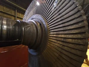
Picture this: You’re standing in a power plant control room, watching the massive steam turbine gradually wind down after a scheduled shutdown. The steam has been cut off, the generator has been disconnected, and all operational systems have been secured. Yet something catches your eye on the monitoring display – the rotor is still turning, slowly but deliberately, hours after the shutdown command was executed.
For new engineers entering the power generation industry, this observation often triggers a moment of confusion and curiosity. The logical expectation would be for the turbine to simply coast to a stop once the driving force is removed, much like a bicycle wheel eventually stops spinning when you stop pedaling. But industrial turbines, particularly large steam and gas turbines, seem to defy this intuitive understanding.
“Why hasn’t the turbine stopped yet?” is one of the most common questions posed by fresh engineering graduates during their first plant tours. The answer lies in understanding a critical but often overlooked component of turbine design: the turning gear system. A turning gear system for a turbine can also be called a jacking gear or, in the context of steam turbines, a barring gear. These terms refer to the same type of device that slowly rotates the turbine’s main shaft to ensure safe operation.
The continuous rotation you’re witnessing isn’t a malfunction or oversight – it’s a carefully engineered solution to some of the most challenging problems facing large rotating equipment.
What is a Turning Gear System?
1. Definition
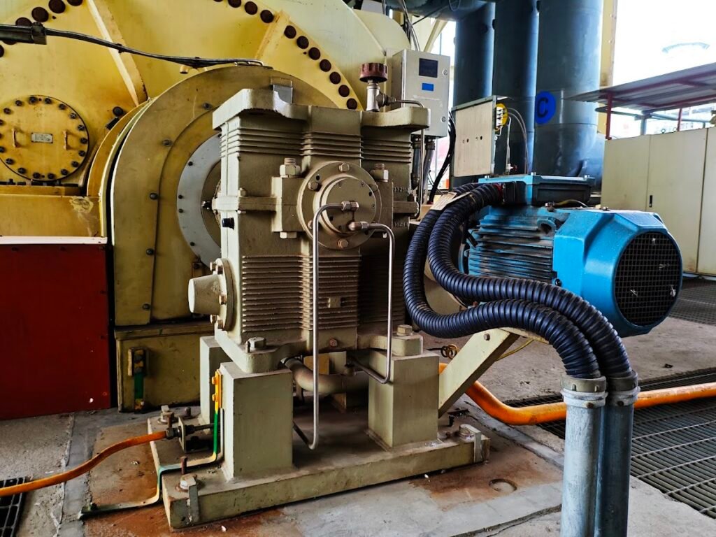
A turning gear- sometimes also called jacking gear or, barring gear in steam turbine- system is a specialized auxiliary drive mechanism designed to rotate large turbine rotors at very low speeds during shutdown periods and maintenance operations. This critical piece of equipment transforms the turbine from a high-speed power generator into a slowly rotating, thermally protected machine that can safely cool down without sustaining damage.
2. Physical Location and Mounting
The turning gear system is strategically positioned for optimal mechanical advantage and maintenance accessibility. Typically, it’s mounted directly on the turbine casing, positioned to engage with the main rotor assembly near one of the bearing housings.
Common mounting locations include:
- Low-pressure turbine end: Most frequent location, where the rotor diameter is largest, providing maximum gear ratio efficiency
- Generator end: Alternative mounting point, particularly in compact installations
- Intermediate casing: Used in multi-shaft configurations or when space constraints require creative positioning
The mounting design ensures the turning gear can be easily serviced without disturbing the main turbine assembly, while maintaining precise alignment with the rotor for reliable engagement.
>>> Checkout modern steam turbine designs here.
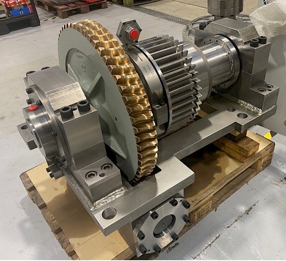
3. Key Components: The Mechanical Architecture
The turning gear system comprises several precisely engineered components, each serving a specific function in the overall protective operation:
- Turning Gear Motor: A low-speed motor that provides the mechanical power needed to rotate the massive turbine rotor. Two primary types dominate modern installations: Electric motors (AC induction motors, most common), Hydraulic motors (requires higher torque).
- Reduction Gearbox: A critical component that reduces the motor’s high rotational speed to the extremely low speeds required for rotor protection. The gearbox typically provides reduction ratios between 100:1 and 300:1, transforming motor speeds of 1,800 rpm down to the required 3-20 rpm rotor rotation.
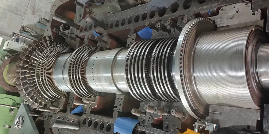
- Turning Pinion: The final drive element that directly engages with the turbine rotor. This small but precisely manufactured gear meshes with a large ring gear machined into or mounted on the rotor assembly to transfer torque from the motor to the rotor.
- Engaging/Disengaging Clutch: Mechanically links or separates the turning gear from the turbine shaft. Automatically disengages before startup to avoid damage.
- Interlocks and Sensors: Safety systems that prevent engagement when the turbine is running at high speeds and monitor proper operation during turning. Interlocks and sensors systems incorporate comprehensive monitoring and safety systems like:
- Speed monitoring
- Position sensing
- Operational interlocks
- Control system integration
Why Do Turbines Need to Keep Turning After Shutdown?
The continuous rotation of turbine rotors after shutdown isn’t arbitrary engineering over-caution – it’s a calculated response to four critical physical phenomena that can cause expensive damage and operational headaches if ignored.
1. Rotor Bow Prevention: Fighting Thermal Distortion
Click to know details about rotor bow prevention.
When a turbine shuts down, different parts of the massive rotor cool at different rates. The top portion of the shaft, exposed to rising hot air, remains warmer than the bottom portion, which cools more rapidly. This temperature differential creates uneven thermal expansion and contraction across the rotor’s diameter.
If the rotor remains stationary during this cooling process, the warmer upper section stays slightly longer while the cooler lower section contracts more quickly. This creates a permanent bend in the shaft – known as thermal bow or rotor bow. Think of it like leaving a plastic ruler near a heat source: one side expands more than the other, causing the entire piece to curve.
2. Bearing Protection: Maintaining the Oil Film Barrier
Click to know how turning keeps the bearing protected from the risk of metal-to-metal contact.
Turbine bearings – both journal bearings that support the rotor’s weight and thrust bearings that control axial movement – rely on hydrodynamic lubrication. This system works by creating a thin film of pressurized oil between the rotating shaft and the bearing surface, preventing metal-to-metal contact.
When rotation stops completely, this protective oil film breaks down and drains away under gravity. The full weight of the rotor then rests directly on the bearing surfaces, creating point loads that can cause permanent indentations, scratches, or “wiping” damage. Continuous slow rotation maintains the oil film integrity, ensuring the bearing surfaces never actually touch.
3. Uniform Cooldown: Preventing Thermal Stress
Click to explore how turning prevents turbine rotor from generating internal thermal stress.
Large turbine rotors contain enormous amounts of thermal energy after shutdown. Without rotation, this heat dissipates unevenly, creating temperature gradients that translate into mechanical stress within the metal structure. Areas that cool faster contract more quickly, while hotter sections resist this contraction, creating internal tensions.
These thermal stresses can exceed the material’s yield strength, leading to micro-cracks, permanent deformation, or even catastrophic failure. Slow rotation ensures heat dissipates uniformly around the rotor’s circumference, maintaining structural integrity throughout the cooldown process.
>>> See how thermal stress for high pressure rotor of steam turbine is calculated. You can also checkout at EPRI research on turbine rotor thermal stress.
4. Startup Reliability: Preparing for the Next Run
Click to learn how turbine is kept in a ‘ready’ state for next startup through rotor turning.
A turbine that has been allowed to develop rotor bow or bearing damage during shutdown will struggle during the next startup sequence. Bent rotors create severe vibration issues that can damage other components, while compromised bearings may fail entirely under operational loads.
By maintaining rotation through the shutdown period, the turbine remains in a “ready” state – geometrically straight, thermally uniform, and mechanically sound – ensuring reliable startup when power generation resumes.
Engineer Insight: Understanding Rotor Bow
What is rotor bow? Rotor bow is a permanent or semi-permanent curvature in the turbine shaft caused by uneven thermal expansion and contraction. Even a bow of just a few thousandths of an inch can create significant problems.
What does a bent shaft mean for turbine performance? A bowed rotor acts like an unbalanced wheel on your car – it creates vibration that increases with rotational speed. In turbines, this manifests as:
- Severe vibration that can damage bearings, seals, and other components
- Reduced efficiency due to increased internal clearances and air leakage
- Potential catastrophic failure if vibration exceeds design limits
- Extended startup times as operators must slowly “straighten” the rotor through controlled heating
- Costly repairs requiring rotor removal and machining to restore straightness
The turning gear system prevents these issues by investing a small amount of energy (typically 5-15 kW) to save potentially millions in repair costs and lost generation revenue.
How the Turning Gear System Works
The turning gear system operates through a carefully orchestrated sequence of events that seamlessly transitions the turbine from high-speed operation to protected low-speed rotation. This process involves precise timing, multiple safety checks, and coordinated system responses to ensure safe operation.
The Operational Sequence: Step by Step
1. Turbine Trip or Shutdown Initiation
When a turbine receives a trip signal or planned shutdown command, the process begins immediately:
- Cutting off the driving force (main steam or gas)
- The rotor begins natural deceleration from operating speed
- Control system automatically prepares turning gear for eventual engagement
- Safety systems begin monitoring rotor speed for engagement readiness
2. Speed Reduction and Interlock Verification
- Speed sensors continuously monitor rotor deceleration
- Engagement is blocked until rotor speed drops below safe threshold
- This interlock prevents catastrophic damage from high-speed gear engagement
- Oil system status is verified to ensure adequate lubrication is available
3. Turning Gear Engagement
Once safety conditions are met, engagement occurs through either Automatic engagement (No operator intervention required) or Manual engagement (Operators can initiate the system).
4. Slow-Speed Rotation Begins
The turning gear motor begins rotating the massive turbine rotor at a precisely controlled speed:
- Rotation speed: 3-20 rpm (dramatically slower than operational speeds)
- Speed is optimized for thermal protection while minimizing mechanical stress
- Continuous rotation ensures uniform heat dissipation around the rotor circumference
5. Oil System Coordination
The lubrication system must remain active throughout turning gear operation:
- Oil pumps continue running to maintain bearing lubrication
- Pressurized oil creates protective films between rotating surfaces
- Oil pressure interlocks prevent gear engagement without adequate lubrication
- Continuous oil circulation prevents bearing damage during slow-speed operation
- Temperature monitoring ensures bearings remain within safe operating limits
6. Clutch Protection During Restart
When the turbine needs to restart, the clutch system ensures safe disengagement:
- Speed differential detection triggers automatic clutch release
- Overrunning clutches automatically disengage when rotor speed exceeds motor speed
- Electromagnetic clutches receive control signals to disconnect electrically
7. Safety Interlocks During Operation
Multiple safety systems prevent engagement during inappropriate conditions:
- High-speed interlocks prevent engagement above safe rotor speeds
- Oil pressure interlocks require adequate lubrication before engagement
- Position sensors confirm proper gear alignment before activation
- Emergency stop circuits provide immediate shutdown capability if needed
- Temperature monitoring prevents operation if bearing temperatures are excessive
Typical Problems & Failure Modes
Even well-designed turning gear systems can experience failures that compromise turbine protection. Understanding these common failure modes helps operators recognize early warning signs and implement corrective actions before minor issues escalate into major equipment damage.
1. Failure to Engage: The Silent Threat
Problem Description: The turning gear system fails to engage automatically or manually after turbine shutdown, leaving the rotor completely stationary during the critical cooldown period.
Common Root Causes:
- Electrical control failures: Blown fuses, tripped circuit breakers, or PLC programming errors
- Mechanical binding: Seized clutch mechanisms or corroded engagement components
- Interlock system faults: Faulty speed sensors providing incorrect rotor speed readings
- Motor failures: Burnt windings, bearing seizure, or starter contactors malfunction
- Hydraulic system issues: Low pressure or contaminated fluid in hydraulic-driven systems
Consequences:
- Thermal bow development: Uneven cooling creates permanent rotor curvature
- Increased maintenance costs and time: Emergency repairs and potential rotor replacement can take significant amount of time and money
Field Recognition Signs:
- Control room alarms indicating “Turning Gear Not Engaged”
- Rotor position indicators showing zero movement
- Absence of motor current draw on turning gear circuits
- Rising differential temperatures across rotor sections
2. Gearbox Failure and Pinion Tooth Wear
Problem Description: Mechanical failures within the reduction gearbox or wear of the turning pinion teeth result in irregular rotation patterns, excessive vibration, or complete mechanical failure.
Common Root Causes:
- Inadequate lubrication: Low oil levels or contaminated gearbox oil
- Overloading: Attempting to turn rotors with thermal binding or mechanical interference
- Material fatigue: Years of intermittent operation causing gear tooth stress cracking
- Misalignment: Improper installation or thermal growth affecting gear mesh
- Contamination: Metal particles from other plant systems entering the gearbox
Consequences:
- Uneven rotation: Creates new thermal gradients instead of preventing them
- Excessive vibration: Can damage adjacent turbine components and foundations
- Complete system failure: Loss of all turning capability during critical periods
- Cascading damage: Gear fragments can damage other gearbox components
Field Recognition Signs:
- Unusual noise levels during turning gear operation
- Irregular motor current fluctuations
- Visible metal particles in gearbox oil samples
- Vibration alarms on turning gear motor or gearbox housing
- Rotor speed variations during constant motor operation
3. Clutch Failure: The Restart Risk
Problem Description: The clutch mechanism fails to disengage properly when the turbine begins restart procedures, creating a mechanical conflict between the turning gear motor and the accelerating turbine rotor.
Common Root Causes:
- Overrunning clutch seizure: Contaminated or corroded clutch bearings prevent free-wheeling
- Electromagnetic clutch failures: Burnt coils or mechanical binding in electrically operated clutches
- Control system errors: Faulty logic or sensor failures preventing disengagement commands
- Mechanical wear: Worn clutch faces or springs losing their designed operating characteristics
- Temperature effects: Thermal expansion causing clutch components to bind
Consequences:
- Turning gear motor damage: Motor destruction from trying to resist turbine acceleration
- Gearbox catastrophic failure: Gear teeth shearing under excessive torque loads
- Safety hazards: Potential for flying debris from gear failures during high-speed operation
Field Recognition Signs:
- High motor current during turbine startup attempts
- Unusual sounds or grinding noises during acceleration
- Vibration spikes as rotor speed increases
- Motor overload protection activation during startup
- Control system alarms indicating clutch position discrepancies
4. Oil System Interlock Failure: The Lubrication Crisis
Problem Description: The interlock systems designed to ensure adequate oil pressure and flow during turning gear operation fail, allowing the system to operate without proper bearing lubrication.
Common Root Causes:
- Pressure sensor failures: Incorrect readings allowing operation with insufficient oil pressure
- Control logic errors: Programming faults bypassing oil system checks
- Oil pump failures: Loss of main or auxiliary lubrication pumps during turning operation
- Piping blockages: Clogged filters or debris in oil supply lines
- Instrumentation drift: Calibration errors in pressure or flow measurement devices
Consequences:
- Bearing damage: Direct metal-to-metal contact causing scoring, wiping, or seizure
- Rotor binding: Damaged bearings creating mechanical resistance to rotation
- Extended repair times: Bearing replacement requires complete turbine disassembly consuming valuable time and money.
Field Recognition Signs:
- Low oil pressure alarms ignored or bypassed
- Rising bearing temperatures during turning gear operation
- Unusual sounds from bearing housings
- Metal particles appearing in oil analysis reports
- Oil system flow rate indicators showing reduced circulation
Prevention and Early Detection Strategies
Proactive Monitoring:
- Regular testing of turning gear engagement during planned outages
- Periodic gearbox oil analysis and vibration monitoring
- Clutch function verification during startup sequences
- Oil system interlock testing and calibration verification
Predictive Maintenance Indicators:
- Trending motor current patterns during operation
- Monitoring gearbox oil temperature and pressure
- Tracking bearing temperatures during turning gear operation
- Recording engagement and disengagement timing consistency
Early recognition of these failure modes allows maintenance teams to address issues during planned outages rather than experiencing emergency failures that can cause extensive collateral damage and extended forced outages.
Best Practices for Engineers
Successful turning gear operation requires disciplined attention to detail and systematic verification procedures. These field-proven practices help prevent equipment damage, ensure reliable operation, and extend system service life through proper operational habits and maintenance awareness.
1. Always Verify Turning Gear Engagement During Shutdown Sequence
Verification Steps:
- Visual confirmation: Check control room displays showing turning gear motor current draw and compare with normal operation
- Speed indication: Verify rotor speed indicators show consistent 3-20 rpm rotation
- Audio confirmation: Listen for the characteristic low-frequency sound of gear engagement
- Time-based checks: Perform verification within 30 minutes of turbine trip to ensure thermal protection begins promptly
2. Ensure Oil Pumps Are Running During Turning Operation
Verification Steps:
- Primary oil pump status: Confirm main AC oil pump operation through control system
- Backup system readiness: Verify DC emergency oil pump availability and automatic start capability
- Pressure monitoring: Check bearing oil supply pressure meets minimum requirements
- Flow verification: Ensure oil flow indicators show adequate circulation to all bearings
- Temperature tracking: Monitor oil supply and return temperatures for proper heat removal
3. Listen for Abnormal Noise or Vibration While in Turning Mode
Acoustic Monitoring:
- Establish baseline sounds: Familiarize yourself with normal turning gear operation noise levels
- Daily listening rounds: Include turning gear in routine equipment inspections during operation
- Frequency analysis: Different sounds indicate different problems:
- High-pitched whining: Gearbox bearing wear or lubrication issues
- Grinding or scraping: Gear tooth wear or contamination
- Knocking or thumping: Loose components or rotor imbalance
- Clicking or ticking: Clutch mechanism problems
4. Never Start Turbine While Turning Gear Is Engaged
Verification Steps:
- Verify control system prevents turbine start signals when turning gear is engaged
- Confirm turning gear motor is stopped and electrically isolated
- Verify clutch disengagement through position indicators
- Document turning gear shutdown time and verification steps
5. Include the Turning Gear in Routine Maintenance and Inspection
Inspection Schedules:
- Visual inspection of motor, gearbox, and coupling components
- Check oil levels in gearbox and hydraulic systems
- Verify control system response and interlock functions
- Test manual engagement and disengagement procedures
- Gearbox oil analysis for contamination and wear particles
- Vibration measurements and trending analysis
- Electrical connection inspection and torque verification
- Clutch mechanism operation testing and adjustment
Emergency Procedures:
- Establish clear protocols for oil system failures during turning operation
- Train operators on manual oil pump starting procedures
- Define action levels for noise and vibration increases
- Establish clear escalation procedures for abnormal conditions
- Establish immediate turbine trip procedures if turning gear engagement is discovered during startup
- Train operators on emergency turning gear shutdown procedures
These practices, when consistently applied, significantly improve turning gear system reliability and help prevent costly equipment failures that can extend turbine outages and compromise plant availability.
>>>Checkout NERC reliability standards for power generation equipment.
Conclusion: Small System, Critical Role
The turning gear system perfectly embodies an essential engineering truth: size doesn’t determine significance. While this compact motor and gearbox assembly may seem insignificant compared to the towering turbine it protects, its role is absolutely vital for turbine safety, alignment, and long-term reliability.
Consider the mathematics of protection: a 15-horsepower turning gear motor, consuming perhaps $50 worth of electricity during a typical shutdown, can prevent rotor bow damage that might cost millions to repair and weeks to correct. This small system stands as the guardian against thermal gradients, bearing damage, and the cascade of problems that follow when massive rotating machinery is left unprotected during its most vulnerable moments.
As you begin your careers in power generation, respect the purpose of systems like the turning gear, even when they seem mundane compared to the impressive scale of the main equipment. The most experienced engineers understand that plant reliability often hinges on these “small” auxiliary systems that newcomers might initially dismiss as unimportant. Remember: the most important systems are often the ones working quietly in the background, protecting the equipment that powers our world. The turning gear system exemplifies this principle perfectly – small in stature, immense in importance, and absolutely essential for reliable power generation.
~Rotormind


One Comment
Comments are closed.