Journal Bearing Design and Troubleshooting for Turbines: Practical Engineering Guide
Welcome Back: From Theory to Practice
Now that you understand the fundamental principles of journal bearings and hydrodynamic lubrication from our previous guide, it’s time to apply this knowledge to real-world journal bearing problems and engineering challenges. Theory provides the foundation, but practical success requires mastering journal bearing design parameters, recognizing failure modes, and implementing effective troubleshooting strategies.
This practical guide transforms your theoretical understanding into actionable expertise. You’ll learn how to select optimal bearing clearances, prevent common failure modes, and diagnose problems before they become costly turbine outages. Every concept builds on the principles you’ve already learned, showing how physics translates into reliable engineering practice.
Whether you’re designing new installations or maintaining existing turbines, this guide provides the practical tools and field-tested strategies that separate theoretical knowledge from real-world expertise.
Design Parameters and Engineering Considerations
The successful journal bearing design requires careful consideration of multiple interrelated parameters. Proper design prevents most journal bearing problems before they occur. The goal is to ensure that the bearing can support heavy loads, operate reliably at high speeds, and maintain stability under varying thermal and dynamic conditions.
1. Load Capacity Analysis
Load capacity represents the fundamental criterion for journal bearing design, determining the maximum loads the bearing can support while maintaining adequate oil film thickness. Unlike rolling element bearings with published load ratings, journal bearing capacity must be calculated based on the specific geometry, operating conditions, and lubricant properties.
The load capacity calculation involves solving the Reynolds equation for the specific bearing geometry and operating conditions. This analysis considers both static loads (rotor weight, gear forces, coupling loads) and dynamic loads (unbalance forces, thermal bow, misalignment effects). The design must ensure that the minimum oil film thickness remains above the critical threshold—typically 0.0005 to 0.001 inches—even under the most severe loading conditions.
Modern bearing design employs sophisticated computational fluid dynamics (CFD) analysis to predict load capacity accurately. These analyses account for oil viscosity variations with temperature, non-Newtonian fluid behavior at high shear rates, and the effects of bearing geometry modifications.
Safety factors for turbine journal bearings typically range from 2.5 to 4.0 times the calculated maximum operating loads. This conservative approach accounts for manufacturing tolerances, installation variations, and the severe consequences of bearing failure in critical turbine applications.
>>> Checkout ASME performance test codes for turbomachinery.
2. Clearance Design Philosophy
Journal bearing design clearance represents one of the most critical decisions in bearing engineering. The bearing clearance directly affects oil film thickness, operating temperature, power loss, and dynamic stability. Too tight, and the bearing runs hot with insufficient oil film thickness; too loose, and excessive vibration and reduced load capacity result.
The optimal clearance depends on shaft diameter, operating speed, applied loads, and thermal conditions. For turbine applications, clearances typically range from 0.001 to 0.003 inches per inch of shaft diameter. However, these values must be adjusted based on specific application requirements and operating conditions.
Thermal expansion effects significantly complicate bearing clearance design. As the turbine reaches operating temperature, differential expansion between the shaft and bearing housing changes the running clearance. The design must account for these thermal effects to ensure adequate bearing clearance under all operating conditions while maintaining optimal performance at normal operating temperatures.
Modern clearance design employs thermal analysis to predict clearance variations throughout the operating cycle. This analysis considers shaft temperature, bearing housing temperature, oil temperature, and the thermal expansion coefficients of all materials involved. The goal is to maintain optimal bearing clearance at normal operating conditions while preventing interference during thermal transients.
3. Oil Supply System Requirements
The oil supply system serves as the foundation of journal bearing design, providing not only lubrication but also cooling and contamination removal. The system must deliver clean oil at the correct pressure, flow rate, and temperature under all operating conditions.
- Pressure Requirements: Oil supply pressure must overcome the bearing’s internal pressure to ensure adequate flow through the bearing. Typical supply pressures range from 15 to 30 psi above the bearing’s internal pressure, with higher pressures required for high-speed applications or bearings with restrictive oil flow paths.
- Flow Rate Considerations: Oil flow rate determines the bearing’s ability to remove friction-generated heat. Insufficient flow leads to overheating, while excessive flow wastes energy and may cause oil foaming. Flow rates typically range from 0.5 to 2.0 gallons per minute per inch of bearing diameter, with higher flows required for high-speed or heavily loaded bearings.
- Temperature Control: Oil temperature critically affects bearing performance through its impact on viscosity and thermal expansion. Supply oil temperatures typically range from 100°F to 140°F, with the exact temperature selected to optimize viscosity for the specific operating conditions. The oil system must maintain temperature stability within ±5°F to ensure consistent bearing performance.
- Filtration Control: The oil supply system must also include filtration to remove contaminants that could damage bearing surfaces or block oil passages. Filtration levels of 10-25 microns are typical for turbine applications, with some high-performance applications requiring even finer filtration.
>>> Checkout turbine oil specifications and performance requirements.
4. Shaft Alignment and Thermal Expansion Management
Proper shaft alignment is crucial for journal bearing performance, as misalignment creates uneven loading that can lead to edge loading, excessive wear, and premature failure. However, achieving and maintaining perfect alignment in large turbines presents significant challenges due to thermal expansion effects.
During operation, turbine components expand at different rates due to temperature differences. The rotor typically runs hotter than the bearing supports, causing the shaft to grow more than the bearing housings. This differential expansion can change shaft alignment significantly, requiring careful analysis and accommodation in the bearing design.
Thermal expansion effects are managed through several approaches. Foundation design allows for predictable movement patterns, while bearing housing designs accommodate thermal growth without binding. Some installations use adjustable bearing pedestals that can be fine-tuned during operation to maintain optimal alignment.
The bearing design itself must tolerate reasonable amounts of misalignment without performance degradation. Tilting pad bearings excel in this regard due to their self-aligning capability, while sleeve bearings may require special edge relief or crowned journal designs to handle misalignment.
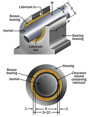
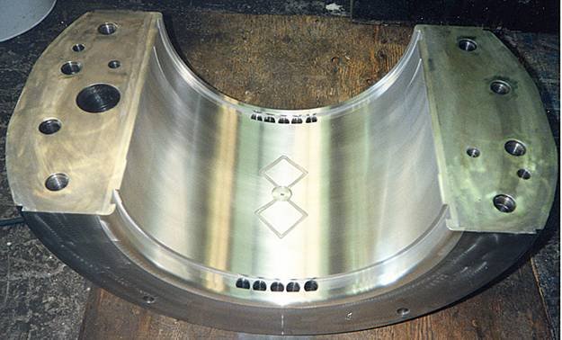
5. Bearing Shell (or Bush) Materials and Selection
The bearing shell material directly contacts the oil film and must provide the right combination of load capacity, conformability, embeddability, and corrosion resistance. Material selection depends on the specific application requirements and operating conditions.
Babbitt (White Metal): Traditional Babbitt alloys, typically tin-based or lead-based, remain the gold standard for many turbine applications. These materials offer excellent embeddability, allowing them to accommodate small particles without scoring the shaft. They also provide good conformability, helping to accommodate minor misalignments and shaft deflections.
Babbitt’s relatively low melting point (around 400°F) provides a safety feature—the bearing material will melt before shaft damage occurs in severe overheating conditions. However, this same characteristic limits operating temperatures and requires careful thermal management.
Bronze Alloys: Copper-lead bronzes offer higher temperature capability and better fatigue resistance than Babbitt, making them suitable for high-speed or high-temperature applications. These materials can operate at higher unit loads and temperatures but sacrifice some of the embeddability and conformability advantages of Babbitt.
Modern Composite Materials: Advanced polymer composites and metal matrix composites offer unique property combinations not available with traditional materials. These materials can provide excellent wear resistance, low friction, and tolerance to marginal lubrication conditions, but their use in critical turbine applications requires extensive testing and validation.
Overlay Coatings: Many modern bearing designs employ thin overlay coatings applied to traditional backing materials. These coatings, typically 0.0005 to 0.002 inches thick, provide optimized surface properties while maintaining the structural benefits of the backing material. Common overlay materials include silver, indium, and specialized polymers.
The selection process must consider not only the bearing material properties but also compatibility with the shaft material, lubricant chemistry, and operating environment. Galvanic corrosion, chemical compatibility, and thermal expansion matching all influence material selection decisions.
Manufacturing Considerations: The bearing shell material must be compatible with the manufacturing processes required to achieve the precise geometry and surface finish needed for optimal performance. Some materials require special machining techniques or heat treatment processes that can affect manufacturing costs and quality control procedures.
Common Problems in Journal Bearings and Prevention Strategies
Despite their reputation for reliability, journal bearings in turbine applications can experience various operational problems that compromise performance and potentially lead to catastrophic failure. Understanding these common issues, their root causes, and early warning signs is essential for maintaining turbine reliability and preventing costly unplanned outages. The most frequent journal bearing problems in turbine applications stem from:
1. Oil Starvation
What it is: Insufficient oil supply to the bearing surface.
Oil starvation represents one of the most serious threats to journal bearing operation, occurring when insufficient lubricant reaches the bearing surfaces to maintain adequate film thickness. This condition can develop gradually or suddenly, but always leads to increased friction, overheating, and eventual bearing failure.
The primary causes of oil starvation include pump failures, blocked oil passages, inadequate oil supply pressure, and system leaks that reduce available flow. In turbine applications, oil starvation often occurs during startup or shutdown when oil pumps may not be operating at full capacity, or during emergency shutdowns when backup oil systems may be inadequate.
Early detection of oil starvation is critical for preventing bearing damage. Warning signs include rising bearing temperatures, increased bearing vibration levels, and changes in oil flow or pressure readings. Modern turbine monitoring systems continuously track these parameters, providing operators with early warning of developing problems.
Prevention strategies focus on maintaining oil system integrity through regular maintenance, redundant oil supply systems, and comprehensive monitoring. Critical turbines often employ multiple oil pumps with automatic backup systems to ensure continuous oil supply even during equipment failures.
2. Misalignment Issues
What it is: When the shaft centerline does not align properly with the bearing axis.
Shaft misalignment creates uneven loading across the bearing surface, leading to edge loading, excessive local pressures, and accelerated wear. In turbine applications, misalignment can result from foundation settling, thermal distortion, improper installation, or mechanical damage to coupling systems.
The effects of misalignment are particularly severe in sleeve bearings, which cannot accommodate geometric variations as effectively as tilting pad designs. Even small amounts of misalignment can create significant stress concentrations that exceed the bearing material’s fatigue limits.
Misalignment manifests through several symptoms including uneven bearing wear patterns, increased bearing vibration at specific frequencies, elevated bearing temperatures, and changes in oil flow distribution. Advanced monitoring systems can detect misalignment through shaft position monitoring and vibration analysis.
Correction of misalignment requires careful shaft alignment procedures during installation and maintenance. Laser alignment systems provide the precision needed for large turbine installations, while thermal growth calculations ensure proper alignment under operating conditions. Some installations incorporate adjustable bearing pedestals that allow for alignment corrections during operation.
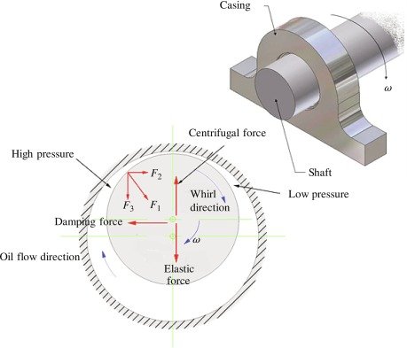
3. Whirl and Whip Instabilities
What it is: Self-excited vibrations due to oil film dynamics — oil whirl is a high-frequency precession of the rotor, while oil whip is a more violent and dangerous form that can become self-sustaining.
Oil whirl and oil whip represent dynamic instability phenomena that can cause severe bearing vibration and potential bearing failure. These instabilities occur when the hydrodynamic forces in the oil film create self-excited oscillations that can grow beyond acceptable limits.
Oil whirl typically occurs at frequencies around 40-45% of shaft rotational speed and results from the natural tendency of the oil film to carry the shaft in a circular orbit around the bearing center. While mild whirl may be acceptable, severe whirl can progress to oil whip—a more dangerous condition where the whirl frequency becomes fixed at the shaft’s first critical speed regardless of operating speed.
Oil whip is particularly dangerous because it can occur at frequencies that coincide with the rotor’s natural frequencies, creating resonance conditions that amplify vibrations to destructive levels. Once established, oil whip can only be eliminated by reducing shaft speed below the whirl onset speed or modifying the bearing design.
Prevention of whirl and whip focuses on bearing design optimization, including proper bearing clearance selection, bearing geometry modifications, and oil supply system design. Tilting pad bearings with optimized preload and pivot locations offer superior stability characteristics compared to sleeve bearings. Some installations employ active control systems that inject controlled oil flows to suppress instability.
4. Contamination Effects
What it is: Foreign particles such as dirt, metal shavings, or water entering the lubrication system.
Contamination of the oil supply system can cause severe bearing damage through abrasive wear, oil passage blockage, and chemical attack on bearing materials. Common contaminants include metallic particles from wear debris, water from seal leaks or condensation, and chemical contaminants from oil degradation or external sources.
Metallic particles are particularly damaging because they can embed in bearing surfaces, creating raised areas that score the shaft or cause localized pressure concentrations. Water contamination affects oil viscosity and can cause corrosion of bearing materials, while chemical contaminants may attack bearing shell materials or oil additives.
The effects of contamination are cumulative—small amounts of contamination may be tolerable initially but can lead to accelerated wear and eventual failure over time. Modern filtration systems can remove many contaminants, but prevention through proper system design and maintenance practices is more effective than treatment after contamination occurs.
Contamination monitoring involves regular oil analysis to detect particles, water content, and chemical degradation products. Trending these parameters over time provides early warning of developing problems and guides maintenance decisions. Some systems employ continuous particle counters that provide real-time contamination monitoring.
5. Overheating Problems
What it is: Excessive temperature in the bearing due to friction or poor cooling.
Excessive bearing temperatures can result from various causes including inadequate oil flow, contamination, misalignment, excessive loading, or oil system problems. Overheating is particularly dangerous because it creates a cascade of problems—reduced oil viscosity leads to thinner films, increased friction generates more heat, and material properties degrade at elevated temperatures.
In Babbitt bearings, overheating can cause the bearing material to soften or even melt, leading to catastrophic failure. Even temperatures well below the melting point can cause permanent changes in material properties that reduce bearing life. Bronze bearings can tolerate higher temperatures but may still experience reduced fatigue life or dimensional changes.
Temperature monitoring is essential for early detection of overheating problems. Modern systems monitor bearing metal temperatures directly through embedded thermocouples or resistance temperature detectors (RTDs). Oil drain temperatures provide additional information about bearing thermal conditions.
Prevention of overheating requires maintaining proper oil flow rates, monitoring oil temperatures, ensuring adequate cooling system capacity, and addressing root causes such as misalignment or excessive loading. Some installations employ emergency cooling systems that activate when temperatures exceed safe limits.
6. Bearing Material Fatigue
What it is: Cracking or flaking of the bearing lining due to repeated loading cycles.
Bearing material fatigue occurs when repeated stress cycles cause crack initiation and propagation in the bearing shell material. This problem is particularly common in applications with varying loads, frequent starts and stops, or misalignment conditions that create stress concentrations.
Fatigue typically begins at the bond line between the bearing material and backing shell, where stress concentrations are highest. Initial cracking may not be visible during routine inspections but can propagate rapidly once established, leading to bearing shell separation and catastrophic failure.
The fatigue process is accelerated by factors such as excessive loading, poor material quality, contamination, and thermal cycling. Babbitt materials are particularly susceptible to fatigue under high loads or temperatures, while bronze materials offer better fatigue resistance but may sacrifice other desirable properties.
Prevention of fatigue failure requires careful attention to bearing design margins, material selection appropriate for the operating conditions, and manufacturing quality control to ensure proper material bonding. Regular inspection programs can detect early signs of fatigue damage before catastrophic failure occurs.
Advanced inspection techniques including eddy current testing, ultrasonic inspection, and microscopic examination can detect fatigue cracks before they become visible to the naked eye. Some facilities employ scheduled bearing replacement programs based on operating hours or cycles to prevent fatigue failures in critical applications.
Journal Bearing Troubleshooting: Field Cases
Effective troubleshooting of journal bearing problems requires a systematic approach that combines understanding of failure mechanisms with practical diagnostic techniques. Real-world bearing problems rarely present with textbook symptoms, making field experience and methodical analysis crucial for accurate diagnosis and appropriate corrective action.
1. Recognizing Key Failure Symptoms
The early detection of journal bearing problems depends on recognizing subtle changes in machine behavior that may indicate developing issues. These symptoms often appear in combination and may evolve as the problem progresses from minor to severe.
I. Vibration Signatures:
Often the first and most noticeable sign; could indicate misalignment, oil film instability, or rotor imbalance.
Changes in vibration patterns provide the earliest and most reliable indication of bearing problems. Healthy journal bearings typically exhibit low vibration levels with minimal sub-synchronous content. The onset of problems manifests through several distinct vibration signatures.
Oil whirl appears as sub-synchronous vibration at approximately 40-45% of running speed, often accompanied by a characteristic “ringing” frequency response. This condition may be intermittent initially, occurring only under certain load conditions or during transient operations. As the instability develops, the whirl becomes more persistent and may progress to oil whip, where the frequency locks onto the rotor’s first critical speed.
Misalignment typically produces increased vibration at running speed (1X) and its harmonics (2X, 3X), with the pattern varying depending on the type and severity of misalignment. Angular misalignment often emphasizes axial vibration, while parallel misalignment affects radial vibration patterns. The vibration may also exhibit directional characteristics, with higher amplitudes in specific orientations.
Bearing wear or damage creates broadband vibration increases across multiple frequencies, often accompanied by increased noise levels. As wear progresses, discrete frequency components may emerge, corresponding to specific mechanical interactions within the bearing assembly.
II. Acoustic Signatures:
Metallic rubbing, knocking, or high-pitched whine can signal loss of lubrication or shaft contact.
Experienced operators can often detect bearing problems through changes in machine sound characteristics. Healthy journal bearings operate with minimal noise, typically producing only the low-frequency sounds associated with oil circulation and shaft rotation.
The onset of bearing problems introduces various acoustic signatures. Oil starvation creates a characteristic “dry” running sound as the hydrodynamic film breaks down. Contamination may produce intermittent scraping or grinding sounds as particles pass through the bearing clearance. Severe misalignment can create periodic knocking sounds corresponding to shaft rotation.
III. Temperature Patterns:
A sudden or continuous increase in bearing metal temperature usually points to oil starvation, contamination, or excessive load.
Temperature monitoring provides critical information about bearing thermal condition and can reveal problems before they become critical. Normal bearing operation exhibits stable temperatures with gradual changes corresponding to load and ambient conditions.
Rising bearing temperatures indicate increased friction losses, potentially from oil starvation, contamination, or misalignment. The rate of temperature rise provides insight into problem severity—gradual increases may indicate developing issues, while rapid temperature rises suggest imminent failure conditions.
Temperature distribution patterns also provide diagnostic information. Uneven temperatures across the bearing circumference often indicate misalignment or uneven loading, while localized hot spots may suggest contamination or material defects.
2. Systematic Diagnostic Approach
Effective bearing diagnosis requires a systematic approach that combines multiple monitoring techniques with understanding of bearing operating principles. The diagnostic process typically follows a structured sequence from initial symptom recognition through root cause identification.
I. Initial Assessment:
The diagnostic process begins with gathering operating history and current machine condition data. This includes recent maintenance activities, operating condition changes, environmental factors, and trending of key parameters. Understanding the machine’s operational context helps focus the diagnostic effort on the most likely failure mechanisms.
Baseline comparison represents a critical aspect of initial assessment. Current operating parameters must be compared with historical baselines to identify deviations and trends. This comparison should include bearing vibration spectra, temperature patterns, oil analysis results, and performance parameters.
II. Systematic Testing:
Diagnostic testing follows a logical sequence designed to isolate the problem source while minimizing risk to the machine. Non-intrusive tests are performed first, followed by more invasive procedures only when necessary.
Coast-down testing provides valuable information about bearing dynamic behavior by observing machine behavior as it passes through various speed ranges. This testing can reveal critical speed interactions, oil whirl onset speeds, and resonance conditions that may not be apparent during steady-state operation.
Load variation testing, where possible, helps differentiate between load-dependent and load-independent problems. Bearing misalignment typically shows little correlation with load changes, while oil film problems may vary significantly with applied loading.
III. Correlation Analysis:
Effective diagnosis requires correlating symptoms across multiple parameters to identify consistent patterns that point to specific failure mechanisms. This analysis often reveals relationships that are not apparent when examining individual parameters in isolation.
3. Common Problem Patterns and Solutions
Oil Starvation
- Symptoms: Rising temperatures, dry running sounds, increased bearing vibration
- Causes: Pump failures, blocked passages, system leaks
- Solutions: Check oil system integrity, verify pump operation, inspect filtration
Misalignment
- Symptoms: Directional vibration patterns, uneven temperature distribution, harmonic content
- Causes: Foundation settling, thermal distortion, installation errors
- Solutions: Laser alignment verification, thermal growth analysis, bearing housing adjustment
Contamination
- Symptoms: Intermittent scraping sounds, gradual temperature rise, oil analysis changes
- Causes: Seal failures, inadequate filtration, external contamination
- Solutions: Enhanced filtration, seal inspection, oil system flushing
Dynamic Instabilities (Whirl/Whip)
- Symptoms: Sub-synchronous vibration, frequency locking at critical speeds
- Causes: Bearing design issues, excessive bearing clearances, oil film dynamics
- Solutions: Bearing design modification, clearance optimization, damping enhancement
4. Advanced Monitoring Techniques
Modern turbine installations employ sophisticated monitoring systems that provide continuous surveillance of bearing condition and early warning of developing problems. These systems have evolved from simple alarm systems to comprehensive diagnostic platforms capable of detecting subtle changes in bearing behavior.
I. Vibration Analysis:
Advanced vibration monitoring goes far beyond simple overall vibration levels to provide detailed frequency domain analysis that can identify specific bearing problems. Modern systems employ multiple accelerometers positioned to capture radial, axial, and sometimes tangential vibration components.
Spectral analysis reveals the frequency content of vibration signals, allowing identification of specific problem signatures. Waterfall plots show how vibration spectra change over time, revealing trends that may not be apparent in instantaneous measurements. Order tracking during startup and shutdown provides insight into speed-dependent phenomena such as critical speeds and oil whirl onset.
Phase analysis compares vibration signals from multiple locations to determine shaft motion patterns. This analysis can distinguish between various types of misalignment, unbalance conditions, and bearing problems based on the relative phase relationships between measurement points.
II. Temperature Monitoring:
Advanced temperature monitoring systems employ multiple sensors strategically located to provide comprehensive thermal surveillance. These systems go beyond simple alarm functions to provide trending, pattern recognition, and predictive capabilities.
Bearing metal temperature monitoring through embedded thermocouples or RTDs provides direct measurement of bearing thermal condition. Multiple sensors around the bearing circumference can detect uneven temperature distributions that indicate misalignment or localized problems.
Oil temperature monitoring at both supply and drain locations provides information about heat generation within the bearing. The temperature rise across the bearing correlates with friction losses and can indicate developing problems before bearing metal temperatures become excessive.
Infrared thermography provides non-contact temperature measurement capability and can reveal thermal patterns not detectable through point measurements. Thermal imaging during operation can identify hot spots, uneven temperature distributions, and thermal gradients that indicate bearing problems.
III. Oil Analysis Programs:
Systematic oil analysis provides insight into bearing condition through examination of wear debris, contamination levels, and oil degradation products. Modern oil analysis programs employ sophisticated techniques that can detect bearing problems in their earliest stages.
Wear debris analysis identifies the source and severity of mechanical wear within the bearing system. Spectrographic analysis quantifies metallic wear particles, while ferrography provides detailed examination of particle morphology and wear mechanisms. Trending wear metal concentrations over time reveals developing problems before they become critical.
Contamination monitoring detects foreign particles that can cause bearing damage. Water content analysis reveals seal problems or condensation issues, while particle counting quantifies solid contamination levels. Acid number trending indicates oil degradation that can affect bearing material compatibility.
5. Repair vs. Replace Decision Matrix
Choosing whether to repair or replace a journal bearing depends on multiple technical, economic, and operational factors—especially critical in turbine applications where failure can be costly or catastrophic.
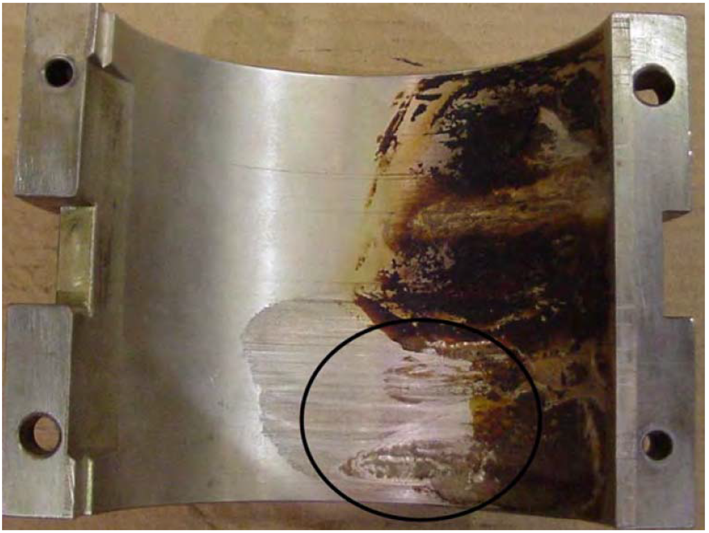
I. Damage Assessment
- Minor damage (light scoring, small embedded particles) → Often repairable by polishing or refinishing.
- Severe damage (deep scoring, cracks, material loss, distortion) → Usually requires full replacement.
Insights: If original specifications and strength can’t be restored, replacement is safer and more reliable.
II. Economic Considerations
- Repair:
- Lower initial cost
- Includes labor, materials, and downtime
- May have shorter service life and require frequent re-inspections
- Replacement:
- Higher upfront cost
- Offers longer life, better reliability
- Enables material upgrades or design improvements
Always Consider lifecycle cost, not just immediate expenses.
III. Operational Requirements
- Critical machines (e.g., main turbine shaft) → Often justify replacement to avoid unplanned shutdowns.
- Emergency situations → Temporary repair may be acceptable, but plan full replacement in the next outage.
IV. Risk Assessment
- Repaired bearings:
- Higher risk of future failure, especially if root cause is unresolved.
- Riskier for high-load, high-speed turbine operations.
- New bearings:
- Offer best reliability.
- Must check compatibility if design/materials differ from original.
From Knowledge to Expertise: Your Complete Journal Bearing Mastery
You’ve now completed the journey from fundamental principles to practical application. Combined with the theoretical foundation from our previous guide, you possess comprehensive journal bearing expertise that spans from hydrodynamic physics to field troubleshooting.
This knowledge represents more than component understanding—it’s systems thinking that applies throughout turbomachinery engineering. The engineer who masters journal bearings understands load distribution, thermal management, vibration analysis, and the critical interactions between mechanical systems and operating procedures.
Most importantly, you now have the tools to prevent journal bearing problems before they occur and solve them efficiently when they arise. In high-stakes turbine environments, this expertise makes the difference between reliable operation and costly failures.
Continue developing this knowledge through field experience, staying current with industry developments, and applying these principles to the unique challenges in your applications. The foundation is solid—now build your reputation as a turbine engineer who truly understands the critical systems that keep the power flowing.
Keep asking, keep analyzing, and keep learning—your bearings depend on it.
~Rotormind


One Comment
Comments are closed.