Instrument Air System Explained: Powering the Nervous System of the Plant
Introduction: The Air You Don’t Feel
“It’s just air, right? Then why does the entire plant trip when it’s gone?”
Walk through any industrial facility—a refinery, chemical plant, or power station—and you’ll witness an orchestra of mechanical precision. Massive pumps circulate thousands of gallons per minute, towering distillation columns separate complex mixtures, and control valves orchestrate flow rates with surgical accuracy. Yet beneath this symphony of steel and process lies an invisible force quietly keeping everything under control: instrument air system. You can’t see it, feel it, or smell it—but when it fails, the plant knows immediately. Alarms blare, valves lock in place, and sometimes, the entire operation grinds to a halt.
The paradox is striking: How does something as fundamental as air become mission-critical when it disappears? Here’s the trick: instrument air system doesn’t provide just air—this compressed, filtered, dried and pressure-regulated air is the nervous system of industrial facilities, carrying the critical control signals that keep processes running safely and efficiently. When a control valve needs to throttle flow, when a safety system must activate during an emergency, or when precise pressure control determines product quality, instrument air delivers the power and reliability that electronic systems alone cannot provide.
In this comprehensive guide, we’ll explore what instrument air truly is, how it’s produced and conditioned to exacting standards, where it’s deployed throughout your facility, and why maintaining its cleanliness, dryness, and consistency isn’t optional but absolutely essential.
What Is Instrument Air?
1. Definition
At its core, Instrument Air is compressed‑air used to operate control valves, actuators, pneumatic tools, and safety systems. The system that incorporates this compressed air is called the instrument air system. Think of it as the muscle behind your plant’s decision-making processes—when a control system determines that a valve needs to open 45% to maintain proper flow, instrument air provides the precise pneumatic force to make it happen.
2. Essential Traits
The essential traits that define quality instrument air are non-negotiable: it must be clean, dry, oil-free, and consistently pressurized. These aren’t just nice-to-have characteristics—they’re fundamental requirements that directly impact system reliability and safety.
To standardize these requirements globally, the industry relies on ISO 8573-1 air quality classifications, which specify acceptable levels of particles, water, and oil content. Most instrument air systems target Class 1 or 2 specifications, ensuring the ultra-clean, dry air that modern control systems demand for optimal performance.
3. How Instrument Air (IA) Differs From Service Air (SA)
Instrument air isn’t just any compressed air. Unlike Service Air (SA), which might power general maintenance tools or equipment cleaning, instrument air operates under far more demanding specifications. Service air can tolerate some moisture, oil carryover, and particulates that would spell disaster for sensitive control equipment. Instrument air, by contrast, must meet stringent purity standards to ensure reliable operation of critical control systems.
| Feature | Instrument Air (IA) | Service Air (SA) |
|---|---|---|
| Purpose | Control valves, actuators, safety systems, precise pneumatic control | General maintenance tools, equipment cleaning, non-critical pneumatic tools |
| Air Quality | • Ultra-clean: ISO 8573-1 Class 1-2 • Particle-free • Bone dry (dew point -40°C or lower) • Oil-free (<0.01 mg/m³) | • Moderate quality: ISO 8573-1 Class 4-6 • Some particles acceptable • Moisture tolerance • Oil carryover permissible |
| Pressure Stability | Critical: ±2% variation typical Consistent 20-30 psig with minimal fluctuation | Less critical: ±10% variation acceptable Variable pressure based on demand |
| Reliabili-ty Priority | Mission-Critical Backup compressors, redundant dryers, emergency backup systems required | Convenience Downtime acceptable, minimal backup systems |
Instrument Air System Layout: Compression to Header
Understanding how raw ambient air becomes high‑quality instrument air means following every stage of the instrument air system treatment train. Each component plays a critical role in achieving the stringent quality standards that control systems demand.
🌬️ Air Intake Filter
- Removes large particles from ambient air
- First line of defense against environmental contaminants
⚙️ Compressor Unit
- Reciprocating or screw-type compression
- Two units configuration: Running + Standby (auto changeover logic)
- Provides system redundancy for continuous operation
❄️ Aftercooler
- Reduces temperature after compression
- Prevents downstream condensation that could damage equipment
💧 Moisture Separator & Drain Trap
- First stage of water removal
- Captures bulk condensate before entering drying system
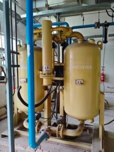
🏜️ Air Dryer
- Twin tower desiccant or refrigerated technology
- Maintains dew point < -40°C for control system reliability
- Critical component for preventing freeze-up and corrosion
🛡️ Air Receiver Tank
- Acts as buffer reservoir for demand fluctuations
- Reduces pressure pulsations that could affect control precision
🔬 Filters
- Microfilters remove residual oil mist and particulates
- Final polishing stage for ultra-clean air quality
📊 Pressure Regulator & Distribution Header
- Maintains stable pressure (~6–7 kg/cm² in most systems)
- Distributes conditioned air to all IA consumers throughout the plant
- Includes pressure monitoring and alarm systems
Where Is the Instrument Air System Used in a Powerplant?
Instrument air’s reach extends throughout every critical system in a power generation facility. Understanding these applications reveals why IA system reliability directly impacts plant availability and safety.
1. Pneumatic Actuators
The workhorses of plant control, pneumatic actuators convert instrument air pressure into precise mechanical motion:
Motor Operated Valves (MOVs)
- Backup pneumatic operators for critical isolation valves
- Emergency positioning when electrical power is compromised
- Fail-safe positioning during plant trips
Control Valves in Critical Systems
- Boiler Feed Pump (BFP) Control: Maintains precise feedwater flow for steam generation
- Condensate System: Regulates condensate flow and hotwell levels
- Lube Oil Systems: Controls bearing oil pressure and temperature for rotating equipment
- Steam Bypass Valves: Manages steam flow during startup and load changes
2. Trip & Interlock Circuits
Safety systems rely on instrument air for immediate, fail-safe responses:
Emergency Shutdown Systems
- Plant-wide safety shutdowns triggered by critical parameter deviations
- Immediate isolation of fuel, steam, and water systems during emergencies
Critical Valve Operations
- ESV (Emergency Stop Valves): Instant fuel cutoff during turbine trips
- CV (Control Valves): Safety positioning during abnormal conditions
- LCV (Level Control Valves): Emergency drain and isolation functions
3. Soot Blowers (Boiler Cleaning)
Essential for maintaining heat transfer efficiency:
- Pulverized Coal Plants: Removes ash deposits from boiler tubes and superheater surfaces
- Biomass Units: Clears fouling from heat exchange surfaces
- Cycling Operation: Automated cleaning sequences during operation
4. Hydraulic Air Assist Systems
Hybrid systems combining hydraulic power with pneumatic control:
- Turbine Control Systems: Air-assisted hydraulic actuators for governor valves
- Heavy Equipment: Pneumatic assists for large hydraulic-operated dampers and gates
5. Maintenance Tools & Equipment
Supporting plant maintenance through dedicated service air taps:
- Pneumatic Tools: Impact wrenches, grinders, and drilling equipment
- Calibration Equipment: Pneumatic test benches for instrument calibration
- Cleaning Systems: Air-powered cleaning tools for maintenance activities
Critical Insight A single instrument air system failure can cascade through all these applications simultaneously, potentially forcing a complete plant shutdown. This interconnected dependency makes IA system reliability non-negotiable for power generation facilities.
▶︎Related reading: our detailed post on the Condensate System shows how valve accuracy depends on a healthy instrument air system.
The Enemies of Instrument Air: Moisture, Oil, and Pressure Drops
1. Moisture: The Silent System Killer
Water in instrument air system creates a cascade of problems that can cripple plant operations:
I. Freezing in Control Lines
- Winter temperatures can freeze moisture in pneumatic tubing, blocking air flow to critical actuators
- Frozen lines prevent safety valves from operating during emergency conditions
- Ice formation can crack tubing and fittings, leading to air leaks and pressure loss
Corrosion and Component Degradation
- Moisture accelerates internal corrosion of pneumatic components and piping
- Rust particles become contaminants that damage downstream equipment
- Long-term exposure reduces component lifespan and increases maintenance costs
Safety System Failures
- Moisture can prevent emergency shutdown valves from responding when needed most
- Trip systems may fail to activate due to water-blocked pneumatic signals
2. Oil Contamination: Precision Equipment’s Enemy
Even trace amounts of oil can compromise instrument performance:
Instrument Damage
- Oil residue clogs precise orifices in pneumatic instruments and positioners
- Contaminated air damages sensitive measurement devices and calibration equipment
- Oil breakdown products create acidic compounds that corrode internal components
Sticky Actuator Operation
- Oil buildup causes actuators to stick or move erratically
- Control valves lose their ability to modulate smoothly, affecting process control
- Sticky operation can prevent valves from reaching their intended positions
3. Pressure Instability: Control System Chaos
Consistent pressure is fundamental to reliable pneumatic control:
Valve Malfunction
- Pressure drops cause control valves to lose their set positions
- Actuators may not generate sufficient force to operate large valves
- Inconsistent pressure leads to hunting and oscillating control behavior
Partial Stroke Problems
- Insufficient pressure prevents valves from achieving full travel
- Safety valves may not fully close or open when required
- Partial strokes can leave systems in unsafe intermediate positions
4. Contamination: The Precision Killer
Particulate contamination wreaks havoc on fine control equipment:
Blocked Control Orifices
- Microscopic particles plug the precise orifices in pneumatic controllers
- Blocked orifices cause erratic control signals and instrument failures
- Fine filters become loading points that require frequent replacement
System-Wide Impact
- Contamination spreads throughout the distribution system
- Multiple instruments fail simultaneously, creating complex troubleshooting scenarios
🎯 Critical Monitoring Requirements
Dew Point Surveillance
- Continuous monitoring ensures moisture levels stay below -40°C
- Trending helps predict dryer regeneration cycles and maintenance needs
- Alarm systems provide early warning before moisture reaches critical levels
Filter Maintenance Programs
- Regular differential pressure monitoring indicates when filters need replacement
- Scheduled maintenance prevents breakthrough contamination
- Proper filter selection ensures adequate protection without excessive pressure drop
Common Problems & Field Symptoms: Diagnostic Chart
|
Problems 976_8673b1-1b> |
Field Symptoms 976_339852-af> |
Possible Causes 976_50bef6-3e> |
Corrective Actions 976_dac283-a1> |
|---|---|---|---|
|
Moisture in System 976_54f405-19> |
|
|
|
|
Oil Contamination 976_eaee1c-ea> |
|
|
|
|
Low System Pressure 976_7bc7f6-50> |
|
|
|
|
Pressure Fluctuations 976_977532-83> |
|
|
|
|
Particulate Contamination 976_bd0df4-ef> |
|
|
|
|
System Leakage 976_756648-bf> |
|
|
|
Diagnostic Tip: Start troubleshooting at the air treatment equipment and work downstream. Many field symptoms that appear to be individual instrument problems actually originate from common system-wide issues in air quality or pressure stability.
▶︎For more diagnostic guidelines and tip sheets for instrument air system, see the US Dept. of Energy’s Compressed‑Air Systems Guidebook.
Engineering Best Practices
Reliable instrument air systems don’t happen by accident—they result from disciplined engineering practices and proactive maintenance strategies. These proven practices have evolved from decades of plant experience and costly lessons learned from system failures. Implementing these guidelines transforms instrument air system from a potential liability into a dependable foundation for plant operations.
1. Redundancy & Backup Systems
Maintain Dual Compressors with Smart Controls:
- Configure automatic changeover logic between running and standby compressors
- Test auto/manual switching quarterly to ensure seamless transitions
- Verify load-sharing capabilities during high-demand periods
- Document switchover times and system response during testing
Critical Load Protection:
- Install low instrument air system pressure interlocks to trip critical drives before damage occurs
- Set trip points well above minimum operating pressure requirements
- Test interlock functionality during scheduled maintenance windows
- Ensure backup power availability for compressor systems during outages
2. Quality Monitoring & Documentation
Systematic Dew Point Surveillance:
- Log dryer dew point readings weekly, trending data for pattern recognition
- Establish alarm setpoints at -35°C to provide early warning before critical -40°C limit
- Document dryer regeneration cycles and correlate with ambient conditions
- Maintain historical records to predict equipment life and replacement needs
Pressure System Monitoring:
- Track header pressure trends and identify gradual degradation patterns
- Monitor pressure drops across major distribution branches
- Document compressor loading cycles and runtime patterns
- Establish baseline performance metrics for system capacity planning
3. Preventive Maintenance Programs
Filter Element Management:
- Replace filter elements strictly per OEM recommendations—never extend intervals
- Monitor differential pressure across filter banks as replacement indicators
- Maintain spare filter inventory based on historical replacement frequencies
- Document filter condition at replacement to identify upstream problems
Receiver Tank Maintenance:
- Drain receiver tanks regularly to prevent water carryover to distribution system
- Inspect internal conditions annually for corrosion or contamination buildup
- Verify drain trap operation and automatic drainage systems
- Test relief valve settings and operation during planned maintenance
4. Safety System Verification
Fail-Safe Testing Programs:
- Test “fail-safe” behavior of pneumatic valves quarterly (spring return operation)
- Verify that safety valves move to their safe position upon air loss
- Document valve stroke times and compare to baseline performance
- Identify valves showing degraded response and schedule maintenance
Emergency Response Preparedness:
- Develop procedures for manual operation during instrument air system loss
- Train operators on backup systems and emergency valve positioning
- Maintain portable air supplies for critical safety system testing
- Practice emergency scenarios through regular drill exercises
5. System Documentation & Training
Comprehensive Record Keeping:
- Maintain detailed P&IDs showing all instrument air system consumers and routing
- Document system modifications and capacity changes over time
- Keep vendor manuals and technical specifications readily accessible
- Track performance trends and correlate with maintenance activities
Personnel Development:
- Ensure maintenance staff understand pneumatic system principles
- Provide regular training on air quality standards and testing methods
- Cross-train operators on instrument air system operation and troubleshooting
- Establish competency requirements for working on safety-critical pneumatic systems
Golden Rule: The cost of implementing these best practices is always less than the cost of the first major failure they prevent. Instrument air system reliability is built through consistent application of proven engineering principles, not reactive maintenance after problems occur.
Safety & Interlocks
1. Mandatory System Protection
Low Pressure Alarm Systems:
- Install redundant pressure transmitters with independent alarm circuits
- Set staged alarm levels: Low alarm at 90% of normal pressure, Low-Low alarm at 80%
- Include pressure trend indicators to predict system degradation before critical levels
Automatic Compressor Changeover:
- Design fail-proof logic that switches to standby compressor without operator intervention
- Implement pressure-based switching with time delays to prevent nuisance transfers
- Provide manual override capability for maintenance and testing purposes
- Include runtime equalization logic to balance wear between compressors
Emergency Backup Systems
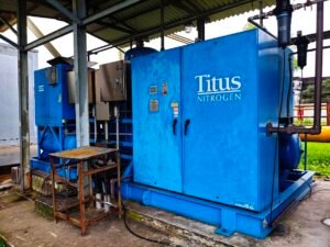
- High-Pressure Nitrogen Cylinders: Provide immediate backup for critical safety systems
- Redundant Air Headers: Separate distribution systems for the most critical applications
- Portable Compressor Connections: Quick-connect points for temporary backup units
- Manual Isolation Capabilities: Allow critical systems to be maintained independently
2. Critical Valve Fail-Safe Design
Fail-Safe Position Engineering
Analyze each valve’s function to determine the safest position upon air loss.
- Fire Protection Systems: Deluge valves fail OPEN to provide water flow
- Fuel Systems: Emergency stop valves fail CLOSED to prevent fuel flow
- Steam Systems: Bypass valves fail CLOSED to prevent turbine overspeed
- Cooling Water: Critical cooling valves fail OPEN to maintain equipment protection
- Vent valves: Vent valves fail OPEN to protect the system from pressure building
3. Safety System Integration
Emergency Shutdown Coordination:
- Integrate IA system status into plant-wide emergency shutdown logic
- Provide early warning to operators before reaching critical pressure levels
- Coordinate with other safety systems (fire protection, gas detection, emergency power)
- Ensure instrument air system failure doesn’t prevent manual emergency actions
Critical Safety Principle: Every instrument air system must be designed assuming it will fail. The question isn’t whether failure will occur, but whether the plant can continue operating safely when it does. Proper safety design and interlocks ensure that instrument air system failure leads to safe shutdown, not catastrophic consequences.
Conclusion: The Powerplant’s Silent Pulse
Instrument air system doesn’t move turbines—but it decides whether turbines move. It doesn’t generate a single kilowatt of electricity—but it determines whether those kilowatts reach the grid safely and reliably. This paradox defines the unique nature of instrument air systems: their power lies not in what they do, but in what they enable others to do. When a 500-megawatt turbine trips offline, the root cause investigation often traces back to a failed control valve, a stuck actuator, or a safety system that couldn’t respond—all dependent on that invisible network of compressed air flowing quietly through the plant’s steel arteries.
Yet despite this critical dependency, instrument air systems are too often treated as simple utilities rather than the sophisticated life-support systems they truly are. The engineers who understand this distinction—who see instrument air system not as background noise but as the plant’s silent pulse that keeps everything alive—are the ones who build truly reliable power generation facilities.
The choice is yours: Will you treat instrument air system as just another utility, or will you recognize it for what it truly is—the nervous system that keeps your powerplant alive? The answer to that question may well determine whether your plant becomes a model of reliability or a cautionary tale of how the smallest systems can bring down the mightiest machines. In the end, every pulse of pressurized air flowing through your instrument system carries with it the potential for either seamless operation or catastrophic failure. Make sure you’re on the right side of that equation.
~Rotormind


One Comment
Comments are closed.