Gas Turbine Compressor Bleed Air Systems Explained: Cooling, Surge Protection, and EFM Technology Guide
The $50 Million Question
At exactly 14:37 on March 15, 2019, a single cooling air valve at the Riverside Power Station stuck closed for just 47 seconds. That’s all it took. The resulting thermal shock cracked the second-stage turbine nozzle, sending metallic debris through a $200 million machine spinning at 3,600 RPM. Total damage: $50 million. Downtime: 127 days, and one sobering lesson about the invisible systems that keep power plants running.
What investigators discovered changed how the engineers think about gas turbine air management. That valve wasn’t just a cooling component – it was part of an integrated system fighting four simultaneous battles every second of operation. While protecting turbine components from thermal destruction, the same air extraction network prevents compressor surge that can shred blades in 30 seconds and optimizes airflow for maximum revenue generation.
This is the story of how compressed air becomes the lifeblood of a gas turbine. How the same molecules extracted from your compressor’s 9th stage can prevent a catastrophic surge during startup, cool a turbine blade spinning faster than a Formula 1 engine, and generate an extra $2 million annually through intelligent flow modulation.
You’re about to discover how Extraction Flow Modulation (EFM) technology transforms simple ‘compressor bleed air’ extraction into a sophisticated revenue-generating system that works around the clock – protecting your investment, preventing disasters, and maximizing profits while you sleep.
Chapter 1: The Heat Challenge Every Engineer Must Solve
Quick Quiz: What temperature do you think the combustion gases reach in a modern gas turbine? A) 800°C B) 1200°C C) 1500°C D) 2000°C+
If you answered D, you’re absolutely right. Modern gas turbines routinely operate with combustion temperatures exceeding 2000°C – that’s hotter than most volcanic lava. Yet somehow, these machines run continuously for months, even years, without melting into expensive scrap metal.
Here’s the shocking truth that every power engineer needs to understand: even our most advanced superalloys begin losing structural integrity around 1200°C. So how do we bridge this 800°C gap between what materials can handle and what thermodynamics demands?
The Engineering Solution: Compressor Bleed Air Cooling
The answer lies in using the turbine’s own compressor as a cooling air factory. Here’s the brilliant engineering: while the turbine generates power, its compressor simultaneously creates high-pressure, high-temperature air that’s still 1100°C cooler than combustion gases. This compressed air becomes our cooling medium, extracted at strategic points and routed through sophisticated distribution networks to protect critical components. This brilliant cooling strategy is called ‘compressor bleed air’ cooling– a phrase often heard of by young engineers in power plants.
Why compressor bleed air instead of external cooling systems? Four critical advantages:
- High pressure: Compressor air reaches 250+ psia, providing the driving force to penetrate tight cooling passages
- High temperature differential: Even “hot” cooling air creates effective heat transfer. When we need to cool components operating at 1500°C, using 400°C air might seem counterintuitive, but remember – it’s still 1100°C cooler than the hot gases
- Ready availability: No external systems required – the compressor runs whenever the turbine operates
- Clean and dry: Filtered and moisture-free, protecting sensitive components
The Journey of Destruction and Protection
Let’s trace how this cooling strategy protects components along the hot gas path:
- Combustion Zone (2000°C+): Where natural gas and compressed air create the inferno that drives your generator
- First Stage Turbine (1500°C): Compressor discharge air (400°C) flows through internal blade passages
- Second Stage (1200°C): 13th stage extraction air (350°C) provides external nozzle cooling (you’ll find out soon about extraction air)
- Third Stage (800°C): 9th stage extraction air (250°C) maintains thermal protection
- Exhaust Section (600°C): Atmospheric air from auxiliary blowers completes the cooling chain
This temperature cascade strategy matches cooling air temperature to thermal load – hotter cooling air where temperatures are extreme, progressively cooler air as gas temperatures decrease. This strategy is required to prevent fatal thermal stress.
The message is clear: your gas turbine’s compressor isn’t just there to supply air for combustion – it’s also your cooling air factory. As air travels through the compressor’s stages, it gains both pressure and temperature, creating the perfect conditions for effective cooling distribution throughout the machine.
Remember:
Every 25°C increase in firing temperature translates to approximately 1% efficiency improvement. In a 400MW plant, that 1% represents millions of dollars in annual fuel savings. But here’s the catch: effective cooling lets turbines run hotter without blade metal losing strengths at higher temperatures. Without sophisticated cooling systems like ‘compressor bleed air’, turbines would be limited to much lower, less efficient operating temperatures.
Chapter 2: Meet Your Cooling Air Sources
To understand how cooling systems work in practice, we’ll examine a real-world example using GE’s 9FA+e gas turbine – a machine that demonstrates the fundamental principles found across all modern gas turbine designs. While extraction points and specific configurations vary between manufacturers (Siemens, Mitsubishi, Ansaldo), the core technology and thermodynamic principles remain consistent across the industry.
Strategic Extraction Points in the GE 9FA+e Design
In our reference machine, air is extracted at three critical locations, each serving specific cooling requirements:
I. 9th Stage Extraction (Low-Pressure Circuit):
- Pressure: ~50-80 psia
- Temperature: ~200-300°C
- Applications: Third-stage nozzle cooling, pulsation protection bleeds
- Design philosophy: Lower pressure, sufficient for less demanding cooling tasks
II. 13th Stage Extraction (High-Pressure Circuit):
- Pressure: ~150-200 psia
- Temperature: ~350-400°C
- Applications: Second-stage nozzle cooling, critical sealing applications
- Design philosophy: Higher pressure for demanding cooling requirements
III. Compressor Discharge (Maximum Pressure):
- Pressure: ~250+ psia
- Temperature: ~400-450°C
- Applications: First-stage component cooling, maximum pressure sealing
- Design philosophy: Highest pressure for most critical cooling needs
Pressure Calculator Example: If your compressor inlet sees standard atmospheric pressure (14.7 psia) and your pressure ratio is 18:1, your discharge pressure will be 14.7 × 18 = 264.6 psia. This high pressure is what makes effective cooling possible throughout the turbine.
While other gas turbine designs may use different stage numbers for extraction (some manufacturers prefer 7th and 11th stages, others use 10th and 15th), the fundamental principle remains: extract progressively higher-pressure air for progressively more demanding cooling applications.
The Five Cooling Circuits You Need to Know
Now that we understand our cooling air sources, let’s explore how this air protects the most critical components in your turbine:
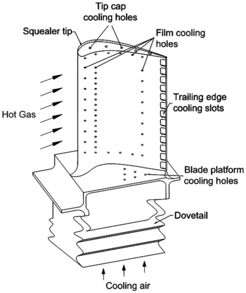
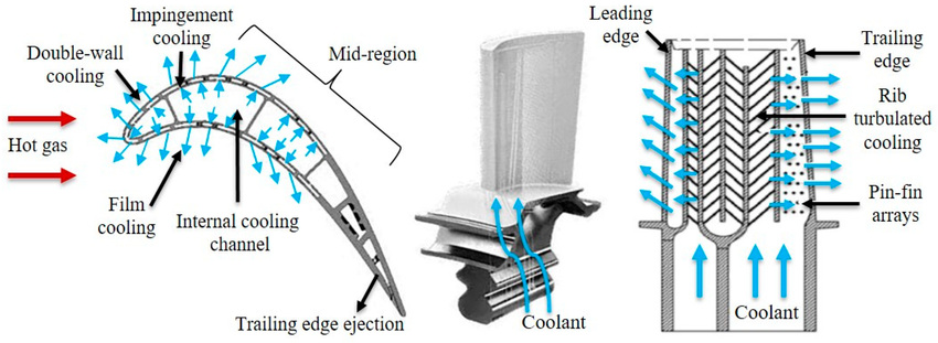
- Bucket (Blade) Cooling: Serpentine internal passages feed cooling air through the rotating blades. These components face the highest thermal stress, spinning at 3,600 RPM while exposed to 1500°C+ combustion gases. Without internal cooling, these blades would melt within minutes, causing catastrophic rotor failure and potentially destroying the entire turbine.
- Nozzle Cooling: External impingement cooling protects stationary vanes that direct hot gases onto the rotating blades. Nozzles experience extreme thermal gradients and must maintain precise aerodynamic shapes under extreme heat. Cooling failure here leads to nozzle warping, reduced efficiency, and potential blade damage from disrupted gas flow.
- Shroud Cooling: Maintains tight tip clearances while preventing thermal distortion of the turbine casing. Proper shroud cooling ensures maximum efficiency by preventing hot gas leakage over blade tips. Even 0.5mm clearance increase can reduce turbine efficiency by 1%, costing hundreds of thousands annually in lost performance.
- Bearing Compartment Cooling: Protects lubrication systems from heat damage and prevents oil degradation. Bearing temperatures above 180°C cause rapid lubricant breakdown, leading to bearing failure and potential rotor seizure. This cooling circuit literally keeps your turbine’s heart beating.
- Exhaust Frame Cooling: Shields downstream components from residual heat and prevents hot gas recirculation into bearing areas. While exhaust gases have cooled to ~600°C, this is still hot enough to damage structural components and create thermal stress that can crack expensive castings.
>>> You can checkout recent cooling advancements of gas turbine airfoils.
Chapter 3: The Pulsation Protection System – Your Turbine’s Safety Net
Now that you understand how compressor bleed air solves the cooling challenge, we need to address a critical operational reality: the same extraction points that provide cooling air can also save your compressor from self-destruction.
Real-World Scenario: It’s 6 AM, and you’re conducting your routine turbine startup. The cooling air system we just studied is ready to protect your hot section components, but there’s another, more immediate threat lurking in your compressor section. Ignore this threat, and within 30 seconds of turbine ignition, you could be looking at compressor blade fragments scattered throughout your turbine casing.
What is the Pulsation Protection System?
This system uses the same 9th and 13th stage extraction points we discussed for cooling, but serves a completely different purpose: preventing compressor surge during startup and shutdown operations. The system that prevents this surge during critical times is called the pulsation protection system.
Understanding Compressor Surge: The Flow Reversal Phenomenon
Compressor surge occurs when airflow through the compressor reverses direction, creating a phenomenon similar to water hammer in pipes, but with far more devastating consequences. Here’s what happens:
During steady-state normal operation, your compressor operates in its “sweet spot” where:
- Airflow rate matches what the combustors can consume
- Pressure rise across the compressor matches system resistance
- Flow velocity through each stage remains stable and forward-directed
Think of it like a water pump: when the pump speed matches the system demand, water flows smoothly from inlet to outlet.
What Goes Wrong During Startup & Shutdown Scenario?
In both startup and shutdown, the core problem is backpressure building faster than the compressor can push air forward.
Startup: The compressor reaches full speed quickly, but combustion is still weak, so the combustors and turbine can’t pass all the air. The trapped air raises system pressure until it forces flow to stall and reverse through the compressor stages—an event that can shake blades violently and cause serious damage.
Imagine your compressor trying to push 1000 kg/s of air into a system that can only accept 600 kg/s. The excess air has nowhere to go, so system pressure builds rapidly. Eventually, this backpressure becomes so high that it exceeds the compressor’s ability to push air forward.
Shutdown- Different Cause, Same Problem: Fuel flow drops instantly, but the compressor keeps moving air due to rotor inertia. With the turbine extracting less energy, backpressure again builds and can trigger the same damaging flow reversal.
The Flow Reversal: When backpressure exceeds the compressor’s pumping capability:
- Forward flow stalls in the rear compressor stages first
- Pressure differential reverses across these stages
- Air flows backward through the compressor passages
- Flow instability propagates forward through the entire compressor
Why It’s Catastrophic: Compressor blades are designed for air flowing in ONE direction. When flow reverses:
- Blade angles become wrong for the new flow direction
- Massive flow separation occurs on blade surfaces
- Violent pressure oscillations create destructive forces
- Blade vibration can exceed material limits in seconds
When Surge Threatens Your Investment?
- During startup: Before combustion stabilizes airflow patterns
- At shutdown: As fuel flow decreases faster than compressor deceleration
- Load rejection: Sudden loss of electrical load creates flow mismatch
- Component fouling: Dirty compressor blades change flow characteristics
The Bleed Valve System: Converting Cooling Points to Safety Systems
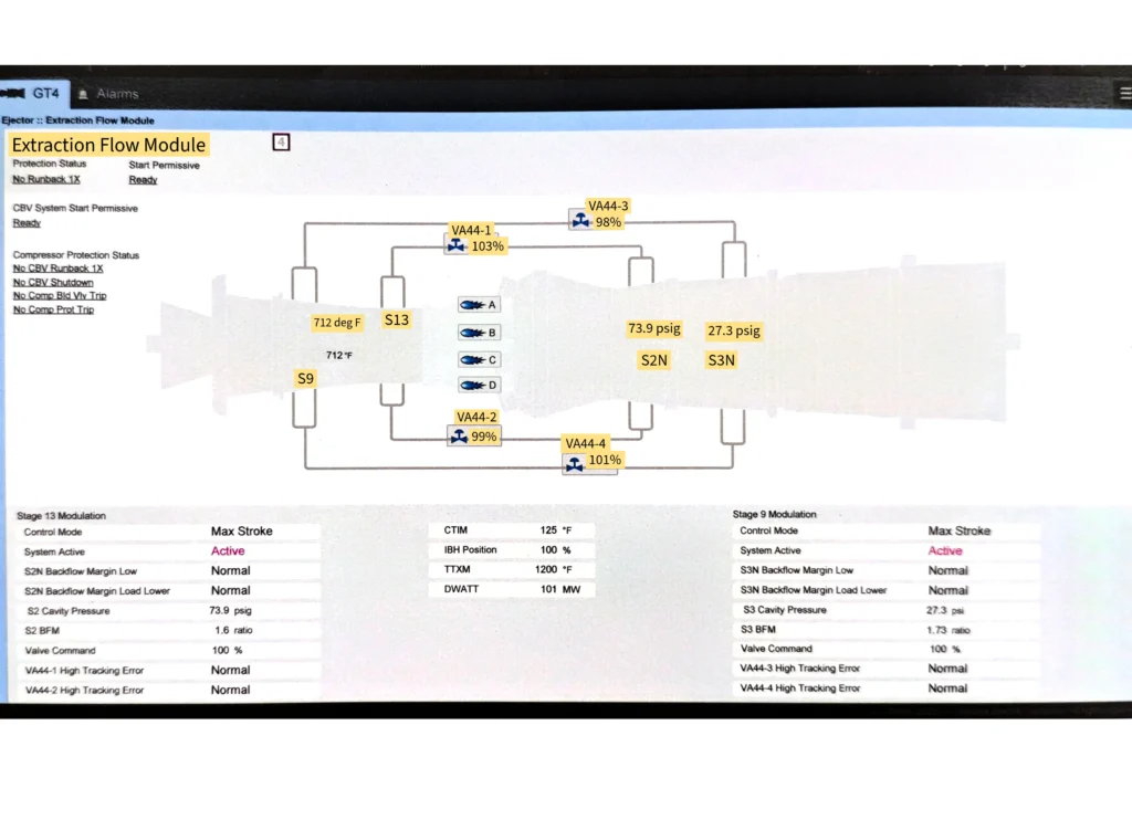
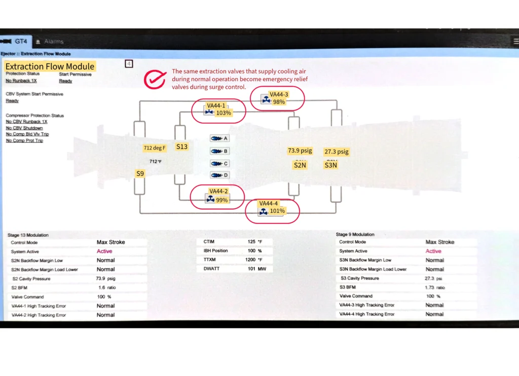
Here’s where the engineering becomes elegant: the same extraction points that supply cooling air during normal operation become emergency relief valves during transient conditions. In our GE 9FA+e example, four pneumatically-operated butterfly valves (designated VA44-1 through VA44-4) tap into both 9th and 13th stage extraction points to bleed air directly to the exhaust stack when surge threatens.
We need those spring-open bleed valves (VA44-1 through VA44-4) because-
- They provide an escape route for excess compressor air
- Prevent backpressure buildup during transients
- Maintain forward flow through critical compressor stages
- Protect against surge until normal operation is established
The beauty is that these valves use the same extraction points that provide cooling air during normal operation – elegant dual-purpose engineering that saves both space and complexity.
Spring-to-Open Design Philosophy: These valves use springs to maintain the open position – a fail-safe design that protects your compressor even during power failures. When instrument air pressure is removed, springs force the valves open, creating an immediate relief path for excess compressor air.
Critical Startup Sequence:
- Pre-startup (Valves Open): Spring force keeps valves open, providing maximum relief capacity
- Turbine Ignition (Valves Remain Open): Air bleeds to exhaust, preventing surge as combustion stabilizes
- Acceleration Phase (Valves Still Open): Protection continues until stable operation achieved
- Normal Operation (Valves Close): Energized solenoids close the bleed valves to maximize efficiency
- Shutdown (Valves Reopen): Solenoids de-energize, valves spring open for protection during coast-down
Engineering Critical Point:
Never attempt turbine startup with closed bleed valves. This single mistake can cause catastrophic compressor damage within seconds, resulting in repairs exceeding $10 million and outages lasting months.
Understanding “Redundancy” vs. “Parallel Operation”
Here’s a crucial distinction that trips up new engineers: although you have four bleed valves connected to the same extraction points used for cooling, they’re not truly redundant. All four valves must function properly to provide adequate surge protection airflow. They’re arranged in parallel to handle the required relief volume, not to provide backup capability.
Chapter 4: Enter EFM Technology – The Game Changer
Before vs. After Comparison: Imagine running your home’s air conditioning at maximum power even when the temperature is perfect. That’s exactly what gas turbines did with cooling air before Extraction Flow Modulation (EFM) technology arrived.
Building on everything we’ve learned – the temperature challenges requiring cooling, the compressor extraction points providing that cooling air, and the safety systems protecting during transients – EFM technology represents the next evolutionary step: intelligent optimization of cooling airflow in real-time.
What is Extraction Flow Modulation?
EFM fundamentally changes how we approach the cooling challenge discussed in Chapter 1. Instead of providing constant maximum cooling regardless of actual thermal load, EFM systems use the same extraction points we studied earlier to deliver precisely the cooling flow required for current operating conditions.
The breakthrough is dynamic control: EFM valves continuously adjust cooling airflow based on real-time turbine operating parameters, delivering component protection when needed while maximizing overall efficiency when thermal loads are lower.
The numbers speak for themselves: EFM technology typically delivers 1-2% efficiency improvements while extending low-load operating capability by 20-30%. In a 400MW plant operating at $40/MWh, that efficiency gain represents over $2.8 million annually in fuel savings.
The Four EFM Valves: Precision Control of Our Extraction Points
Remember those 9th and 13th stage extraction points from our GE 9FA+e study? EFM technology adds sophisticated modulating valves to these same circuits, transforming simple extraction points into intelligent cooling management systems.
S2N Circuit (Second-Stage Nozzle Cooling):
- Valves: VA44-1 and VA44-2 control 13th stage extraction air
- Operating pressure: ~150-200 psia (matching our earlier discussion)
- Flow range: 5-100% of maximum design flow
- Purpose: Protect second-stage nozzles with variable cooling based on thermal load
S3N Circuit (Third-Stage Nozzle Cooling):
- Valves: VA44-3 and VA44-4 manage 9th stage extraction air
- Operating pressure: ~80-150 psia (consistent with extraction point characteristics)
- Flow range: 5-100% of maximum design flow
- Purpose: Provide optimized third-stage nozzle cooling
Each valve transforms the simple “on/off” extraction concept into precision flow control through:
- Digital positioners: Precision control with accuracy
- Position feedback transmitters: Real-time position monitoring
- Trip solenoid valves: Emergency full-open capability
- Air filter regulators: Clean, regulated instrument air supply
EFM Operation: A Three-Phase Strategy
Phase 1: Startup Mode (Minimum Flow) During turbine startup, while the pulsation protection system (Chapter 3) handles surge prevention with its bleed valves, EFM valves position at their minimum mechanical stops (~5% open). This provides essential component cooling while maximizing airflow available for combustion and surge protection. Think of this as “survival mode” – just enough cooling to prevent thermal damage.
Phase 2: Turndown Enhancement (Strategic Flow Increase)
Once flame detection confirms successful ignition and the surge protection system transitions to normal operation, EFM valves implement turndown enhancement. This might seem counterintuitive, but here’s the brilliant engineering: more cooling air means less air available for combustion, forcing higher combustion temperatures that enable better fuel mixing and lower emissions at reduced loads.
Phase 3: Performance Optimization (Dynamic Modulation) Above minimum emissions-compliant load, EFM valves shift to their most sophisticated mode: real-time modulation based on component thermal protection requirements. The system continuously balances cooling effectiveness against power generation efficiency.
What is Turndown and How EFM Improves It
Turndown capability is the lowest load at which a gas turbine can operate while still meeting emissions limits. For example, a 400 MW machine might be limited to 160 MW (40%) in traditional operation, but with enhanced turndown it could run cleanly at 120 MW (30%). Greater turndown means more flexibility to match grid demand or market conditions.
Once combustion is stable after startup, EFM valves take over and—counterintuitively—open further at low loads to extract more cooling air. This reduces the air available for combustion, which raises combustion temperature, improves fuel–air mixing, and results in cleaner, more complete combustion.
Why is less combustion air better at low load? At part load, the turbine is burning less fuel, but the compressor still delivers nearly the same mass of air. This excess air cools the flame too much, lowering combustion temperature and causing incomplete fuel burn—leading to high CO and unstable flames. By diverting some of that excess air to cooling, EFM restores the ideal fuel–air ratio, keeping the flame hot enough for clean combustion while still protecting components.
The physics works because firing temperatures are already lower at low load, so extra cooling air doesn’t stress components. In fact, it adds a safety margin while improving combustion stability. EFM continuously monitors load, emissions, and component temperatures, adjusting cooling flow in real time, and reducing extraction if temperatures approach limits.
Older fixed-flow systems couldn’t “trade” cooling air for combustion quality, so they were stuck with higher emissions and limited turndown. EFM’s intelligent, dynamic control extends the low-load range, increases operational flexibility, and creates new revenue opportunities without compromising safety or equipment life.
The Control Strategy: Protecting Components While Maximizing Efficiency
EFM control strategy builds directly on the temperature cascade principle from Chapter 1, using the extraction points detailed in Chapter 2 to maintain optimal pressure ratios across turbine nozzle cooling cavities:
- Pressure monitoring: Triple-redundant transmitters (96-S2N and 96-S3N) continuously measure cavity pressures at the same extraction points used for cooling
- Ratio calculation: Control system computes pressure ratio between cooling cavity and calculated gas path pressure
- Flow adjustment: EFM valves modulate to maintain predetermined pressure ratios that ensure adequate cooling
- Backflow protection: System prevents hot gas from entering cooling passages by maintaining positive pressure differential
- Fault response: Any sensor failure triggers automatic valve opening for component protection
Interactive EFM Troubleshooting Guide
- Problem: Valve position doesn’t match command signal
Root Cause Analysis: Since these valves control the same extraction points used for cooling, position errors can affect both thermal protection and efficiency
Solution: Check instrument air supply pressure, calibrate digital positioner, inspect valve mechanism for binding
- Problem: Cavity pressure reading anomalies
Root Cause Analysis: These pressure measurements directly relate to cooling effectiveness at the extraction points
Solution: Verify sensor calibration, clear sensing lines, replace faulty transmitter
- Problem: EFM trip solenoid fault alarm
Root Cause Analysis: Trip solenoids provide fail-safe protection similar to the spring-open design in surge protection valves
Solution: Test solenoid coil resistance, verify air supply, exercise valve manually
- Problem: Position feedback error
Root Cause Analysis: Inaccurate position feedback affects the precision control that makes EFM effective
Solution: Clean and adjust limit switches, check wiring continuity, inspect mechanical linkages
Chapter 5: Supporting Cast – The Unsung Heroes
Component Tour: While EFM valves grab the spotlight, successful cooling systems depend on numerous supporting components. Let’s meet the unsung heroes that keep everything running smoothly.
Cooling Blowers: Your Backup Cooling Team
When compressor bleed air isn’t available or sufficient, auxiliary cooling blowers step in:
I. Exhaust Frame Cooling Blowers:
- Purpose: Cool exhaust frame and third-stage aft wheel space
- Capacity: Each sized for 100% cooling requirement
- Operation: Lead-lag arrangement (one runs, one stands by)
- Protection: Automatic switchover if operating blower fails
II. No. 2 Bearing Area Blowers:
- Purpose: Provide cooling air to rear bearing compartment
- Features: Inlet filtration to prevent bearing contamination
- Control: Pressure switches monitor performance
- Safety: Check valves prevent reverse flow
Instrumentation: Your Information Network
Pressure Monitoring:
- Compressor discharge transmitters (96CD-1, -1B, -1C): Triple-redundant measurement for control calculations
- Cavity pressure transmitters: Monitor cooling effectiveness in real-time
- Blower pressure switches: Detect cooling system failures instantly
Temperature Surveillance:
- Thermocouples: Monitor hot gas path temperatures
- RTDs: Track cooling air and bearing temperatures
- Exhaust temperature arrays: Calculate firing temperature limits
Position Feedback:
- Valve limit switches: Confirm critical valve positions
- Analog position transmitters: Precise valve position data for control optimization
Monthly Maintenance Checklist:
✅ Blower Systems:
- Inspect inlet filters for contamination
- Verify automatic switchover logic
- Test pressure switch operation
- Check motor space heater operation
✅ Valve Systems:
- Exercise EFM valves through full range
- Verify position feedback accuracy
- Test trip solenoid operation
- Inspect air supply lines for leaks
✅ Instrumentation:
- Check transmitter calibration dates
- Verify alarm setpoint accuracy
- Test emergency shutdown logic
- Clean sensing line connections
Chapter 6: Putting It All Together
Understanding individual components is important, but mastering their integration is what separates good engineers from great ones. Let’s trace cooling air from compressor inlet to final discharge:
- Air enters compressor at atmospheric conditions
- Compression process increases pressure and temperature through 17 stages
- Extraction points at 9th and 13th stages provide cooling air
- EFM valves modulate flow based on operating conditions
- Distribution networks route air to critical components
- Cooling passages transfer heat from hot metal to cooling air
- Discharge points expel heated air to atmosphere or exhaust stream
Test Your Knowledge:
Question 1: What happens if EFM valves fail closed? Answer: The fail-safe design prevents this – valves fail to full-open position to prevent component overheating.
Question 2: Why aren’t the four compressor bleed valves truly redundant?
Answer: All four valves are required to provide adequate surge protection airflow – they’re parallel, not redundant.
Question 3: When do cooling blowers automatically switch from lead to lag operation? Answer: When pressure switches detect low discharge pressure from the operating blower.
The mastery of cooling systems separates competent engineers from exceptional ones. These invisible systems work tirelessly behind the scenes, enabling the reliable generation of electricity that powers our modern world. Understanding them deeply not only enhances your technical credibility but also positions you as a valuable asset to any power generation organization.
~Rotormind