Generator Excitation System in Action: Field Engineer’s Guide
Welcome Back: Connecting the Dots
In Part 1— “Generator Excitation System Fundamentals: What Every Power Engineer Should Know“, we covered the fundamentals of excitation systems – what they are, how they work, and the different types. We explored how these systems maintain generator voltage stability through precise control of the magnetic field, and examined the three main categories: static excitation systems, AC excitation systems, and DC excitation systems.
Remember that AVR (Automatic Voltage Regulator) we discussed in Part 1? The one that acts as the “brain” of your excitation system, constantly monitoring and adjusting to maintain perfect voltage output? Today you’ll see it in action across different plant types. You’ll learn how to troubleshoot it like a pro, understanding not just what to do when alarms sound, but why certain failures occur and how to prevent them.
By the end of this post, you’ll have the practical knowledge to walk into any power plant and immediately understand how their excitation system is configured, what challenges they face, and how to optimize performance for maximum reliability and efficiency.
Real-World Applications: Where You’ll Actually See These
After several years in the field, I can tell you that every power plant has its own personality when it comes to excitation systems. Let me walk you through what you’ll actually encounter out there.
I. Steam Power Plants
Typical Setup: Static excitation with digital AVR – exactly what we covered in Part 1. You’ll see thyristor-based power electronics feeding the rotor directly through slip rings.
Special Considerations: These plants run hot and carry massive electrical loads. The excitation system needs to handle continuous duty at high ambient temperatures, often in dusty coal plant environments. The large generator inertia means the system doesn’t need lightning-fast response, but it must be rock-solid reliable.
Common Issues: Thermal cycling is your biggest enemy here. Every startup and shutdown stresses the slip rings and brushes. I’ve seen generators trip offline during grid disturbances because the excitation system couldn’t handle the sudden current surges during synchronization.
Student Question: “Why is static excitation preferred here?”
Simple economics and reliability. Static systems have fewer moving parts than rotating exciters, and when you’re dealing with 500MW+ units that cost thousands per minute of downtime, you want proven technology. Plus, the response time is adequate for base-load operation where load changes are gradual.
II. Gas Turbine Plants
Typical Setup: You’ll see both AC and static excitation here – remember our comparison from Part 1? The choice often depends on the manufacturer and vintage of the unit.
Special Considerations: These plants are built for speed. Fast start-up from cold iron to full load in under 30 minutes. Many also provide black start capability – they can energize a dead grid without external power. This puts unique demands on the excitation system during startup sequences.
Common Issues: Rapid load changes are the norm, especially in peaking units. The excitation system sees frequent step changes that can stress the power electronics. Frequency variations during grid disturbances can also cause hunting in older AVR systems.
Student Question: “How does fast response help with peaking duty?”
Think about it – when grid frequency drops and you need to pick up 50MW in seconds, your excitation system needs to boost field current immediately to maintain voltage as the generator loads up. A sluggish excitation system means voltage sags, which can cascade into larger grid problems.
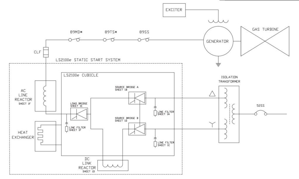
>>> I explained the details of this diagram here: “Gas Turbine Starting: How Three-Phase Power Creates a Rotating Magnetic Field”
III. Hydroelectric Plants
Typical Setup: AC excitation with brushless systems – remember those from Part 1? AC exciter and rotating rectifier assembly all spinning together on the same shaft.
Special Considerations: Hydro units have massive speed variations during startup and shutdown. The excitation system must maintain field control from zero speed through synchronization. Plus, these plants often sit idle for months during dry seasons, then run continuously during high water periods.
Common Issues: Water level changes affect the generator’s cooling, which impacts the excitation system’s thermal management. I’ve troubleshot units where seasonal temperature swings caused control instability. Environmental conditions are harsh – moisture, temperature swings, and limited access for maintenance.
Student Question: “Why don’t we use DC excitation in modern hydro plants?”
Brushless systems eliminate the maintenance headache of slip rings and brushes in remote locations. When your plant is at the bottom of a canyon and maintenance crews need helicopter access, you want systems that can run for years without touching them. The rotating rectifiers are sealed units that handle the harsh environment much better than exposed slip rings.
IV. Wind Turbines
Typical Setup: Electronic excitation systems integrated with power converters. These aren’t your grandfather’s synchronous generators – we’re dealing with doubly-fed induction generators and full-converter systems.
Special Considerations: Variable speed operation is the name of the game. The excitation system must work seamlessly with power electronics to maintain grid code compliance while extracting maximum energy from fluctuating wind conditions.
Common Issues: Fluctuating wind creates constant load variations. Grid stability requirements are stringent – the system must ride through voltage sags and provide reactive power support. Lightning strikes are also a major concern in exposed locations.
Troubleshooting and Common Problems: When Things Go Wrong
Let me share something that took me years to learn: most excitation system failures follow predictable patterns. I’ve been called out at 3 AM more times than I care to count, and the problems are usually variations of the same four issues. Here’s what you need to know to diagnose them quickly and safely.
Most Common Issues New Engineers Face
I. Loss of Excitation
This is the big one that will wake you up at night. Your generator suddenly loses its magnetic field, and you’ve got seconds to act before it becomes a motor and potentially damages the turbine.
Causes: Field breaker trips, fuse failures, brush problems, or AVR power supply issues. I once tracked down a loss of excitation to a loose connection that had been arcing for weeks.
Symptoms: Generator current spikes, power factor goes leading, frequency rises if you’re islanded. The generator will start absorbing reactive power from the grid.
Immediate Actions: Trip the generator immediately – don’t try to troubleshoot with it online. Remember that control loop we discussed in Part 1? When it breaks, there’s no feedback to maintain stability.
II. Over-Excitation
This sneaks up on you because the generator keeps running, but you’re slowly cooking the stator windings.
Causes: Usually AVR failures or incorrect setpoints. I’ve seen operators accidentally bump the voltage setpoint during routine adjustments.
Symptoms: High stator current, overheating alarms, reactive power output higher than normal. The V/Hz ratio climbs dangerously.
Prevention: This is where limiting functions come in. Your V/Hz limiter and maximum excitation limiter should catch this before damage occurs. Regular calibration of these limits is critical.
III. Voltage Instability
Your voltage swings up and down like a yo-yo, and the grid operators are calling you every five minutes.
Causes: Poor AVR tuning, loose connections, or interaction with other generators. Load changes can expose marginal stability.
Solutions: Check your AVR gain settings first. Too high and you get oscillations, too low and you get poor regulation. I keep a standard set of tuning parameters that work for most situations.
IV. AVR Failure
When your digital brain dies, you need backup plans.
Backup Systems: Modern plants have redundant AVR channels. Know how to transfer between them without losing the generator.
Manual Operation: You can run a generator manually by controlling field current directly, but it takes skill and constant attention. Practice this during outages when stakes are low.
Diagnostic Techniques
I. Visual Inspection
Your eyes are your best diagnostic tool. I start every troubleshooting session with a thorough visual inspection.
What to look for: Burnt components, loose connections, oil leaks, unusual wear patterns. Check brush condition and slip ring surfaces. Look for signs of overheating – discolored components, melted insulation.
Straight From the Field: Use a thermal camera if available. Hot spots often indicate problems before they cause failures.
II. Electrical Testing
Numbers don’t lie, but you need to know what they mean.
Key measurements: Field voltage and current, stator voltage and current, power factor, frequency. Compare these to nameplate values and recent trends.
Testing sequence: Start with the easy stuff – power supply voltages, fuse continuity, control signals. Work your way up to more complex measurements like loop response.
III. Trending Analysis
This is where experience pays off. Patterns emerge over time that predict failures.
What to trend: Brush current, field voltage variations, temperature readings, vibration levels. Modern plant computers make this easy.
Spotting problems: Gradual increases in field current might indicate stator winding degradation. Increasing voltage variations could mean AVR component aging.
Straight From the Field: I once caught a failing field breaker six months before it would have failed catastrophically. The current trend showed micro-interruptions that gradually increased in frequency.
Safety Considerations
I. High Voltage Hazards
Field winding voltages can reach 500V or more, and the stored energy in the field can be lethal even after the generator trips.
Key points: Always assume circuits are energized. Use proper PPE. Never work alone on high voltage systems. Field discharge resistors can get extremely hot.
II. Rotating Equipment
Generators don’t stop immediately when you hit the emergency stop. That massive rotor has tremendous inertia.
Safety practices: Verify zero energy state before approaching. Watch for loose clothing or tools. Maintain proper clearances around coupling guards.
III. Lockout/Tagout
This isn’t just paperwork – it’s life insurance.
Proper procedures: Lock out all energy sources – electrical, mechanical, pneumatic. Tag each lockout with your name and date. Test circuits to verify they’re dead before working.
Personal experience: I’ve been saved by LOTO procedures more than once. The extra five minutes spent on proper lockout is worth a lifetime of safety.
Case Studies – “Real Stories from the Field”
These aren’t textbook examples – they’re real situations that taught me lessons I’ll never forget. Each one cost someone time, money, or sleep, but the knowledge gained was invaluable.
Case Study 1: The Mysterious Voltage Fluctuation
The Problem
I got called to a 150MW gas turbine plant where the generator voltage was oscillating every 3-4 seconds. The operators were pulling their hair out because the voltage would swing from 13.5kV to 14.2kV in a regular pattern, like a sine wave. The grid dispatcher was threatening to disconnect the unit.
The Investigation
My first instinct was to check the AVR. I pulled up the oscilloscope and watched the voltage feedback signal – sure enough, it was rock steady. The problem wasn’t the measurement. Next, I checked the field current – it was oscillating in perfect sync with the voltage. Something was making the AVR hunting.
I started with the basics from Part 1: checked the proportional gain, integral time constant, and derivative settings. The proportional gain was set at 50 – way too high for this particular generator. I also noticed the integral time constant was set to 0.1 seconds, which was creating a feedback loop that was just fast enough to cause instability.
The Solution
I reduced the proportional gain to 20 and increased the integral time constant to 0.5 seconds. The oscillations stopped immediately. The AVR knowledge from Part 1 saved the day – understanding that control loop behavior is all about balancing response speed with stability.
Lesson Learned
This happened because the commissioning team had copied settings from another plant without understanding the specific generator characteristics. Every generator has its own personality, and you can’t just copy-paste AVR parameters. I now keep a standard commissioning checklist that includes proper AVR tuning as a mandatory step.
Case Study 2: The Excitation System That Saved the Grid
The Scenario
Summer 2018, peak demand day. A transmission line fault caused a cascade of events that dropped 800MW of generation in less than 30 seconds. I was in the control room of a 300MW coal plant when it happened. The grid frequency dropped to 59.4 Hz, and generators were tripping left and right.
The Response
Our unit stayed online, but barely. The excitation system went into overdrive – field current jumped from 2,800 amps to 4,200 amps in seconds as the AVR tried to maintain voltage while picking up the lost load. The under-excitation limiter kicked in twice to prevent the generator from going unstable.
I watched the sequence of events unfold on the plant historian later. The digital AVR responded in milliseconds, exactly as designed. The voltage dipped to 95% for about 2 seconds, then recovered as the excitation system provided the reactive power needed to stabilize the grid.
Technical Details
The under-excitation limiter was the unsung hero. As the generator picked up real power, its ability to provide reactive power decreased. The limiter sensed this and gradually reduced the field current to keep the generator within its capability curve. Without it, we would have lost synchronism and tripped offline like the others.
Lesson Learned
Backup systems and protective functions aren’t just nice-to-have features – they’re what separates a good excitation system from a great one. That day, our plant helped stabilize the entire regional grid because someone decades ago had invested in proper protection systems.
Case Study 3: The Type Selection That Made All the Difference
The Problem
A 50MW hydro plant in the mountains where the excitation system was failing every six months. The maintenance costs were astronomical, and the utility was considering selling the plant. The problem? They had installed a static excitation system with slip rings and brushes in a harsh mountain environment.
The Investigation
Looking back at comparison table, this was a classic mismatch. The plant operated seasonally – shut down for three months in winter, then ran continuously during spring runoff. The static excitation system with slip rings couldn’t handle the thermal cycling and moisture exposure.
The slip rings were corroding during the winter shutdown, and the brushes were wearing excessively due to the stop-start operation. Every spring startup required brush replacement and slip ring reconditioning. The maintenance crew spent more time on the excitation system than on the turbine itself.
The Solution
We retrofitted the plant with a brushless AC excitation system. Yes, it cost $800,000 upfront, but the payback was immediate. The rotating rectifiers were sealed units that could handle the environmental conditions. No more slip rings, no more brushes, no more seasonal maintenance headaches.
Lesson Learned
Understanding the different excitation system types isn’t just academic knowledge – it’s about matching the right technology to the right application. The original designers had chosen static excitation because it was cheaper, but they didn’t consider the total lifecycle costs. Sometimes the most expensive solution upfront is the cheapest in the long run.
Personal note: That hydro plant is still running the same excitation system 12 years later with minimal maintenance. The plant manager sends me a Christmas card every year thanking me for those extra vacation days he no longer spends fixing brushes.
Putting It All Together: Your Complete Understanding
The Journey So Far
We’ve taken you from theory to practice in these two posts. In Part 1, you learned the fundamentals – what excitation systems are, the three main types (static, AC, and DC), and how AVRs work as the control brain. Now in Part 2, you’ve seen how that knowledge applies across different plant types, from coal plants dealing with thermal cycling to wind farms managing variable conditions.
More importantly, you’ve gained practical troubleshooting skills that textbooks can’t teach. You know what to look for when voltage starts oscillating, how to diagnose loss of excitation, and why proper AVR tuning matters. That’s the difference between book knowledge and field-ready expertise.
Next Steps in Your Learning Journey
Essential Reading:
- IEEE Std 421.5: “Recommended Practice for Excitation System Models” – the Bible for excitation systems
- “Synchronous Generators” by Ion Boldea – deep dive into generator theory
Professional Development:
- IEEE Power & Energy Society courses on power system stability
- Generator protection and control seminars (usually offered by major manufacturers)
Industry Standards to Master:
- IEEE 421.1 through 421.5 series – excitation system definitions and models
- IEC 60034 series – rotating electrical machines standards
- IEEE C50.13 – cylindrical rotor synchronous generators
Final Thoughts
You now have both the theoretical foundation and practical insights to tackle excitation systems confidently in your career. Whether you’re commissioning a new plant, troubleshooting at 3 AM, or making design decisions, you understand not just the “what” but the “why” behind excitation system behavior.
The field stories I’ve shared aren’t just entertainment – they’re the kind of experience that typically takes years to accumulate. Use them as mental references when you encounter similar situations.
Remember, every expert was once a beginner. The key is to never stop learning from each plant, each problem, and each solution. The excitation system that challenges you today will be routine tomorrow.
~Rotormind


One Comment
Comments are closed.