Generator Excitation System Fundamentals: What Every Power Engineer Should Know
Introduction: “Why Should I Care?”
Ever wondered why the voltage at your home stays remarkably steady at 120V (or 230V) despite millions of devices switching on and off across the power grid every second? Or how a generator knows exactly when and how much voltage to push into the grid without overloading it? Behind the scenes, there’s a small but powerful system working nonstop to keep things balanced—the generator excitation system.
Imagine your car’s accelerator pedal. Press it down, and your engine produces more power. Ease off, and it produces less. A generator’s excitation system works similarly – it controls how much “magnetic force” your generator applies to create electricity, but instead of controlling speed, it controls voltage. The more you excite the generator’s rotor, the stronger the magnetic field, and the higher the excitation voltage becomes, allowing it to produce more electrical output.
Just like your car needs that accelerator to respond to driving conditions, generators need excitation systems to respond to electrical demand. Without them, generators would be like cars stuck in neutral – lots of potential, but no way to control the output. Here’s the real kicker— if an excitation system fails during operation, it can destabilize the generator so badly that entire sections of the power grid can go dark. In 2003, a cascade of failures (including excitation system problems) left 55 million people without power across the northeastern United States and Canada. That’s the power of these “invisible” systems.
But here’s the good news – understanding how they work isn’t rocket science. It’s actually quite logical once you grasp the basic concepts. By the time you finish reading, you’ll understand: What excitation systems actually do (hint: they’re not just for starting generators), Why they’re absolutely critical for keeping power plants running smoothly, the core principles behind how all excitation systems work. Don’t worry – we’ll keep the technical jargon to a minimum and explain everything in plain English.
Ready to dive in? Let’s start with the fundamentals and discover why excitation systems truly are the heart that keeps power plants beating.
The Fundamentals: What Exactly Is an Excitation System?
The Basic Concept
Simple Definition: The system that creates and controls the magnetic field in a generator.
Think of an excitation system as the heart of any electrical generator. Just as your heart pumps blood to keep your body functioning, the excitation system provides the essential magnetic field that allows a generator to produce electricity. Without this magnetic field, the spinning rotor inside the generator would accomplish nothing more than moving air around.
At its core, an excitation system is a carefully orchestrated collection of components that work together to create, maintain, and control the strength of the magnetic field in a generator’s rotor. This magnetic field is what transforms mechanical rotation into electrical energy.
>>> Remember How Gas Turbine Starts Using Rotating Magnetic Fields?
The Chicken-and-Egg Problem: “How do you make electricity to make electricity?”
Here’s the classic brain teaser: To create a magnetic field strong enough for power generation, you need electricity to energize the field windings. But if you’re trying to start up a generator, where does that initial electricity come from? You can’t exactly plug your generator into itself!
This classic engineering puzzle has several solutions. Some systems use permanent magnets to provide initial excitation, while others rely on residual magnetism left in the iron core from previous operation. Modern systems often use auxiliary power sources or battery banks to “bootstrap” the excitation process. Once the generator starts producing power, it can then supply its own excitation current.
Key Point: Without excitation, a generator is just an expensive paperweight.
This isn’t hyperbole. A generator without proper excitation literally cannot produce usable electricity. The mechanical energy from a steam turbine, diesel engine, or water wheel means nothing without the magnetic field to convert that motion into electrical energy. The excitation system is what transforms a collection of copper windings and iron cores into a functioning power source.
The Essential Components
1. Exciter: The “starter motor” of the electrical world
The exciter is a small generator whose sole job is to provide DC power to the main generator’s field windings. Think of it as the electrical equivalent of a starter motor in your car – it gets things going. Modern exciters are typically brushless AC machines that feed their output through rotating rectifiers to supply DC current to the main field windings.
In many systems, the exciter is mounted on the same shaft as the main generator, spinning at the same speed. This mechanical coupling ensures reliable operation and eliminates the need for separate drive systems.
2. Automatic Voltage Regulator (AVR): The “brain” that makes decisions
The Automatic Voltage Regulator (AVR) is the intelligent control system that monitors the generator’s output and makes real-time adjustments to maintain stable voltage. It continuously compares the actual output voltage to a reference setpoint and adjusts the excitation current accordingly.
Modern AVRs are sophisticated electronic devices that can respond to voltage changes in milliseconds. They don’t just maintain steady voltage – they also protect the generator from overexcitation, under-excitation, and other potentially damaging conditions.
3. Field Windings: The “muscles” that create the magnetic field
The field windings are copper coils wrapped around the generator’s rotor poles. When DC field current flows through these windings, they create the magnetic field necessary for power generation. The strength of this field current directly determines the generator’s output voltage.
These windings must be carefully designed to handle the required current while withstanding the mechanical stresses of high-speed rotation and the thermal stresses of electrical losses.
4. Sensing Circuits: The “eyes and ears” that monitor everything
The sensing circuits are the feedback network that keeps the Automatic Voltage Regulator informed about system conditions. They monitor output voltage, current, frequency, and other critical parameters. Potential transformers (PTs) step down the high generator voltage to safe levels for measurement, while current transformers (CTs) provide proportional current signals.
These sensing circuits must be highly accurate and reliable since the entire excitation system depends on their feedback for proper operation.
Basic Operating Principle
1. Initial excitation: getting started
When starting up, the system needs an initial source of DC power to energize the field windings. This comes from residual magnetism in the generator’s iron core, permanent magnets, or an external power source. This residual magnetism creates a small initial excitation voltage, allowing the generator to begin producing a measurable output voltage as it spins up.
2. Voltage sensing and feedback
As soon as the generator produces measurable output, the sensing circuits begin monitoring the voltage and feeding this information back to the AVR. The AVR compares this actual voltage to its programmed reference setpoint.
3. Field current adjustment
Based on the voltage feedback, the Automatic Voltage Regulator adjusts the excitation current flowing to the field windings. If the output voltage is too low, the AVR increases field current to strengthen the magnetic field. If voltage is too high, it reduces field current accordingly.
4. Voltage regulation
This process continues continuously during operation. The Automatic Voltage Regulator makes constant small adjustments to maintain the desired output voltage despite changes in load, speed, or other operating conditions. The response time is typically measured in milliseconds, ensuring stable power output.
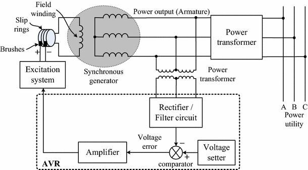
The basic feedback loop: The generator produces AC output, voltage sensing circuits monitor this output, the AVR processes this information and controls the exciter, which provides DC current to the field windings, which creates the magnetic field in the main generator.
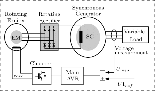
Explaining the Figure: Step-by-step operation (what actually happens in normal use)
- Setpoint chosen: Operator sets U1_ref (desired terminal voltage).
- Generator produces voltage: Exciter produces AC → rectifier converts it to DC → DC energizes main rotor → main rotor magnetic field induces voltage in stator. The generator output is AC (usually 11 kV, 15 kV, or more).
- Sensing & feedback: A potential transformer (PT) & rectifier circuit in the sensing unit (voltage measurement) converts the AC output from the generator to a scaled-down DC signal (U_mes). Terminal voltage U_mes is measured and compared with U1_ref.
- AVR action: AVR output is a low-power DC control signal that drives the chopper. If U_mes < U1_ref, AVR increases the command to the chopper → chopper increases v_exc to exciter field → exciter AC amplitude increases → rectified DC increases → main field current rises → terminal voltage rises back toward setpoint.
- Continuous regulation: This feedback loop runs continuously and rapidly to hold voltage within tight limits, even during load steps or disturbances.
Confusion Buster Box
What’s the Function of Chopper? How It Increases/Decreases Current?
The chopper is basically a DC–DC converter (think of it like a dimmer switch for DC). It takes in a fixed DC supply (from batteries, auxiliary bus, or rectifier). By rapidly switching on and off (PWM – pulse width modulation), it controls the average DC voltage applied to the exciter field winding.
- Longer ON time → more average voltage → higher exciter field current
- Shorter ON time → less voltage → lower field current
That controlled current creates the magnetic field in the exciter machine.
So the chopper is a “valve” that controls how much current excites the exciter field.
Why Not Feed the Chopper Output Current (DC) Directly to the Generator Rotor? Why the AC → Rectifier → DC Detour?
The main generator rotor requires hundreds to thousands of amps of DC. Supplying that through slip rings/brushes would cause huge wear, sparking, and maintenance headaches. Instead, engineers invented the brushless exciter system:
- Feed a small exciter machine via brushes/slip rings (low current, manageable).
- The exciter generates AC on the rotor, which is then rectified by shaft-mounted diodes right next to the main rotor.
- This way, huge DC currents flow inside the rotor without leaving the shaft (no brushes needed).
Brushless excitation = no brushes for the big generator rotor, only for the small exciter. That’s why we don’t connect the chopper directly to the main field.
Types of Excitation Systems: The Different Flavors
DC Excitation Systems
I. What it is: Traditional system using DC generators.
DC excitation systems represent the original approach to generator excitation. These systems use a separate DC generator (called a DC exciter) to provide the direct current needed for the main generator’s field windings. It’s the grandfather of all excitation systems – simple, straightforward, and mechanical.
II. How it works: DC exciter driven by the main shaft.
The DC exciter is typically mounted on the same shaft as the main generator, spinning at the same speed. This mechanical coupling means when the main generator turns, the DC exciter turns with it, producing the DC current needed for excitation. The DC exciter itself has its own field windings that are controlled by the voltage regulator to adjust the excitation level.
Carbon brushes make physical contact with a commutator on the DC exciter, transferring the generated DC power as field current to the main generator’s rotor windings. It’s a direct, mechanical solution to the excitation problem.
III. Pros: Simple, reliable, tried-and-true technology
- DC systems are mechanically straightforward with fewer electronic components to fail. Maintenance staff can easily understand and troubleshoot them.
- They’re robust and can operate for decades with proper care.
- The technology is well-established, with extensive field experience and readily available spare parts.
IV. Cons: Maintenance-heavy, slower response
- The carbon brushes require regular inspection and replacement. The commutator needs periodic maintenance to ensure proper contact.
- Response time is slower compared to modern systems because of the mechanical and electrical time constants involved.
- The system also has more rotating parts subject to wear.
AC Excitation Systems
I. What it is: Modern system using AC exciters with rectifiers
AC excitation systems evolved from DC systems to eliminate many of the maintenance issues associated with brushes and commutators. Instead of generating DC directly, these systems generate AC power and then convert it to DC using rotating rectifiers mounted on the generator shaft.
II. How it works: AC exciter + rotating rectifier assembly
An AC exciter (typically a three-phase machine) generates AC power while rotating with the main generator shaft. This AC power feeds into a rotating rectifier assembly – essentially a collection of diodes that spin with the rotor. The rectifiers convert the AC to DC field current, which then flows directly to the main generator’s rotor windings without any brush contacts.
The whole system is brushless, with the only electrical connection being the stationary control circuits that regulate the AC exciter’s field current.
III. Pros: Better response, less maintenance, more precise control
- Without brushes and commutators, maintenance requirements drop significantly.
- The system responds faster to control signals because there are fewer mechanical limitations.
- Modern electronic controls provide more precise voltage regulation and better integration with plant control systems.
IV. Cons: More complex, requires sophisticated controls
- The control systems are more complex, requiring skilled technicians familiar with power electronics.
- The rotating rectifier assembly, while reliable, is more sophisticated than simple brush contacts.
- Initial cost is typically higher than DC systems.
Static Excitation Systems
I. What it is: Stationary equipment feeding the rotor via slip rings
Static excitation systems break away from the shaft-mounted exciter concept entirely. Instead, all the excitation equipment remains stationary, and power is delivered to the rotating field windings through slip rings and brushes. “Static” refers to the fact that the excitation equipment doesn’t rotate.
II. How it works: Controlled rectifiers fed from unit transformer
The system draws AC power from the generator’s own output (through a unit transformer) or from the station auxiliary supply. Controlled rectifiers (typically thyristors) convert this AC power to variable DC, which is then fed to the generator’s field windings via slip rings. The control system can rapidly adjust the field current from zero to maximum rating in milliseconds, providing superior response compared to rotating machinery.
III. Pros: Fastest response, most flexible control, highest reliability
- Static systems provide the fastest response to system disturbances because there are no rotating electrical machines in the excitation circuit.
- Control flexibility is excellent, allowing for sophisticated control strategies.
- Reliability is high because the excitation equipment is stationary and easily accessible for maintenance.
IV. Cons: Slip ring maintenance, higher initial cost
- The slip rings and brushes require regular maintenance, though typically less than DC commutator systems.
- Initial cost is higher due to the sophisticated power electronics and control systems.
- The system also requires a reliable auxiliary power source during startup.
Comparison Table: DC, AC and Static Excitation Systems
| System Type | Response Time | Maintenance Cost | Best Application |
|---|---|---|---|
| DC Excitation | Slow (2-5 seconds) | High | Older plants, hydro installations |
| AC Excitation | Medium (0.5-2 seconds) | Medium | Most modern power plants |
| Static Excitation | Fast (0.1-0.5 seconds) | Medium-High | Large thermal/nuclear plants |
>>>These classifications follow the IEEE 421.5 standard for excitation system models used in power system stability studies.
The Automatic Voltage Regulator (AVR): The Brain of the Operation
What Does the AVR Actually Do?
Primary Function: Maintains constant terminal voltage
The Automatic Voltage Regulator’s main job is deceptively simple: keep the generator’s output voltage steady regardless of changing conditions. When electrical load increases, voltage tends to drop. When load decreases, voltage tends to rise. The AVR counteracts these changes by continuously adjusting the generator’s excitation current.
Think of it like cruise control in your car. Just as cruise control maintains constant speed by adjusting the throttle, the AVR maintains constant voltage by adjusting the magnetic field strength.
Secondary Functions: Power factor control, reactive power management
Beyond voltage control, modern Automatic Voltage Regulators can also manage reactive power flow and power factor. In power systems, reactive power is like the foam on a beer – you need some, but too much or too little causes problems. The AVR can adjust excitation to control how much reactive power the generator produces or absorbs.
Some AVRs can switch between voltage control mode and power factor control mode depending on system needs. This flexibility makes them valuable tools for grid stability.
The Control Loop: Sense → Compare → Adjust → Repeat
The AVR operates on a continuous feedback loop that happens thousands of times per second:
- Sense: Monitor the generator’s output voltage
- Compare: Check if it matches the desired setpoint
- Adjust: Change the excitation current if needed
- Repeat: Start the cycle again immediately
The AVR continuously monitors both the generator output and the excitation voltage to maintain optimal field strength for stable operation. This constant monitoring and adjustment is what keeps your lights steady even when your neighbor turns on their air conditioner.
Key Parameters and Settings
I. Voltage Setpoint: The target voltage
This is the fundamental setting – the voltage the AVR tries to maintain. It’s typically set to the generator’s rated voltage but can be adjusted for specific operating requirements. For example, a 13.8 kV generator might have its setpoint adjusted to 13.5 kV or 14.1 kV depending on system needs.
The setpoint can usually be adjusted remotely from the control room, allowing operators to fine-tune voltage for optimal system performance.
II. Droop Setting: How voltage changes with load
Droop is an intentional slight reduction in voltage as load increases. Without droop, multiple generators connected to the same system would fight each other, with one generator trying to carry all the load while others do nothing.
A typical droop setting might be 3%, meaning the voltage drops 3% from no-load to full-load. This allows generators to share reactive load naturally without complex coordination systems.
III. Time Constants: How fast the system responds
Automatic Voltage Regulators have adjustable time constants that control response speed. Fast response prevents voltage fluctuations but can cause system instability if too aggressive. Slow response maintains stability but might allow unacceptable voltage variations.
Typical settings balance these competing requirements. The response time might be set to correct 95% of a voltage error within 0.5 seconds – fast enough for good regulation but slow enough to avoid oscillations.
IV. Limiting Functions: Protection against over-excitation
Automatic Voltage Regulators include protective functions to prevent damage from excessive excitation current. Over-excitation limiters prevent the generator from overheating due to excessive field current. Under-excitation limiters prevent loss of synchronism due to insufficient excitation.
These limiters act like safety valves, temporarily overriding normal voltage control when necessary to protect the equipment. They’re typically set based on the generator’s thermal and stability limits as determined by the manufacturer.
Understanding the Big Picture: How It All Fits Together
Now that we’ve covered the individual components and systems, let’s step back and see how excitation fits into the bigger picture of power generation. Understanding these connections helps explain why excitation systems are so critical to reliable power generation.
Generator Operation Without Excitation
What happens: No voltage output, no power generation
Without excitation, a generator becomes nothing more than a spinning mass of copper and steel. Here’s why: electricity generation depends on a magnetic field cutting through conductors. No magnetic field means no voltage induction, regardless of how fast the rotor spins. The mechanical energy from the prime mover is completely wasted, converted only to heat from friction and air resistance.
Why it matters: Understanding the critical role
This stark reality highlights why excitation systems are absolutely essential, not optional equipment. Every kilowatt of electrical power depends on proper excitation. When excitation fails, the generator immediately stops contributing to the electrical grid, potentially causing blackouts or forcing other generators to pick up the load.
Generator Operation With Proper Excitation
Voltage control: Maintaining steady output
With proper excitation, the generator becomes a controlled voltage source. The Automatic Voltage Regulator (AVR) continuously adjusts the magnetic field strength to maintain stable voltage despite changing loads. When someone turns on a large motor, the generator’s voltage tries to dip, but the excitation system responds within milliseconds to maintain steady output.
Power factor control: Managing reactive power
Proper excitation also enables the generator to control reactive power flow. By adjusting excitation above or below the level needed for voltage control, the generator can supply reactive power to the grid (over-excited) or absorb reactive power from the grid (under-excited).
This capability is essential for maintaining grid voltage stability across the entire power system. Large generators act as reactive power sources that help keep transmission line voltages within acceptable limits.
Grid stability: Contributing to overall system health
Well-controlled excitation systems contribute to overall grid stability. During system disturbances, generators with fast-responding excitation can help dampen oscillations and maintain synchronism. This is particularly important in large interconnected power systems where disturbances can propagate across vast distances.
Modern excitation systems often include power system stabilizers (PSS) that provide additional damping signals to improve system-wide stability.
Common Misconceptions
“Excitation is just for starting” – Wrong! It’s continuous
One of the most persistent misconceptions is that excitation is only needed to start the generator. In reality, excitation is required continuously during operation. The moment excitation is lost, the generator immediately stops producing power, even if it continues spinning.
The excitation system works constantly, making thousands of small adjustments every second to maintain proper voltage and reactive power output. It’s not a one-time startup function – it’s an ongoing operational requirement.
When troubleshooting generator issues, technicians often check the excitation voltage first, as it’s a reliable indicator of system health.
“More excitation = more power” – Actually controls voltage, not power
Another common confusion is thinking that increasing excitation increases power output. This isn’t correct. Excitation primarily controls voltage and reactive power, not real power (kilowatts).
Real power output depends on the mechanical input from the prime mover and the electrical load connected to the generator. Excitation adjusts the magnetic field strength to control voltage level and reactive power flow. While there are some secondary effects on real power, excitation is fundamentally a voltage and reactive power control system.
“All excitation systems are the same” – Each type has specific applications
Many people assume that all excitation systems perform the same function in the same way. While the end goal is similar, the three main types (DC, AC, and static) have significantly different characteristics, maintenance requirements, and optimal applications.
DC systems are simple but maintenance-intensive. AC systems offer better performance with moderate maintenance. Static systems provide the best performance but require sophisticated controls. Choosing the wrong type for a specific application can lead to poor performance, high maintenance costs, or operational problems.
Understanding these differences helps explain why power plant engineers spend considerable time selecting the right excitation system for each application, rather than simply choosing the cheapest option.
What’s Coming Next?
In our next post, we’ll explore:
- How these systems actually work in different types of power plants?
- Troubleshooting: Ever wondered what happens when things go wrong? We’ll cover the most common problems and how to fix them.
- Career insights: We’ll share practical tips that will make you sound like a seasoned engineer.
The Foundation: Understanding these basics is essential for Part 2
These fundamentals form the foundation for everything we’ll cover in Part 2— “Generator Excitation Systems in Action: From Theory to Practice“. When we discuss troubleshooting a hunting generator, you’ll need to understand how the Automatic Voltage Regulator control loop works. When we explore different plant applications, you’ll need to know why static excitation might be chosen over AC excitation for a particular installation.
The concepts we’ve covered – magnetic field generation, feedback control, system types, and operational principles – are the building blocks for more advanced topics. Take time to make sure you understand these basics before diving into Part 2.
Ready to dive deeper? Generator Excitation Systems in Action: From Theory to Practice will transform you from someone who understands excitation theory into someone who can work confidently with these systems in the real world. We’ll see you there!
~Rotormind


2 Comments
Comments are closed.