Condensate System Explained: Closing the Steam-Water Loop
Author |Rotormind
Introduction: Why Condensate Recovery Matters
“What goes up as steam must come down as water”
In a thermal powerplant, steam drives the turbine to generate electricity. But what happens to that steam after it has expanded and delivered its energy? It doesn’t vanish—it condenses back into water. That’s where the condensate system steps in. Inside it, steam is cooled and converted back into liquid water—called condensate. In the bigger picture, the condensate system connects the back end of the turbine to the front end of the boiler. It may not be the most glamorous part of the cycle, but it is a critical bridge—both thermally and operationally.
So why does condensate recovery matter?
Every pound of steam in your facility will eventually condense back into water and that hot condensate isn’t waste water. It’s liquid gold carrying 15-25% of your original steam’s heat energy, plus gallons of expensive treated water that cost you money to prepare. Smart condensate recovery delivers a triple win: efficiency through fuel savings when hot condensate returns to your boiler, water conservation by reclaiming every drop of treated feedwater, and cycle continuity that keeps your steam-water loop running as the closed system it was designed to be.
The numbers don’t lie. Proper condensate recovery can slash fuel costs by 10-15%, eliminate thousands of gallons in makeup water requirements, and extend boiler life by reducing thermal shock and maintaining optimal water chemistry.
Ready to close the loop and capture every BTU? Let’s dive into how condensate systems work and why getting them right transforms operational expenses into measurable returns.
Condenser: One of the Main Components of Condensate System
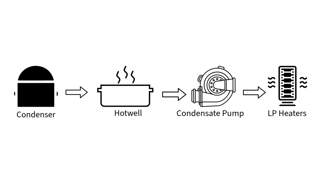
Understanding condensate systems means knowing the critical components that make steam-to-water recovery possible. Here are the four main components that form the backbone of any effective condensate recovery system:
Condensate System Main Components
1. Surface Condenser: Where Steam Becomes Water
Click to learn how surface condenser works
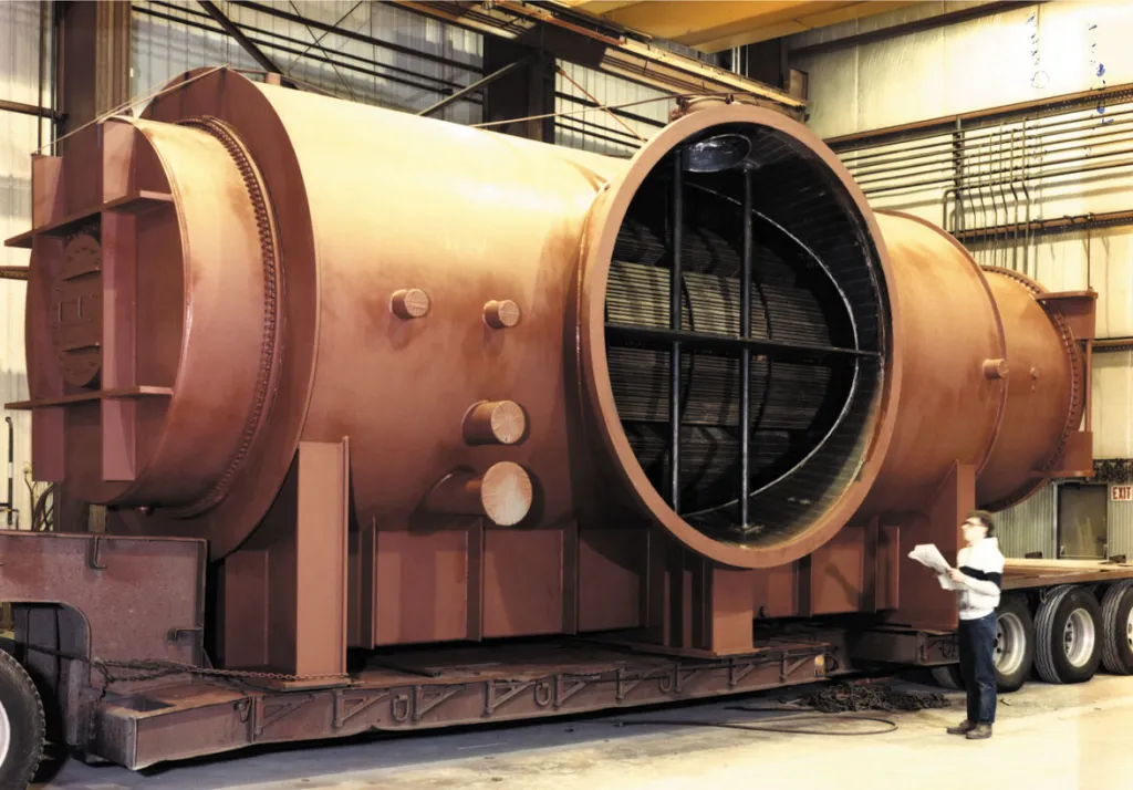
The surface condenser serves as the primary heat exchanger where exhaust steam from turbines or process equipment transforms back into liquid water. Unlike direct contact condensers, surface condensers keep the condensate separate from cooling water, preserving water quality for boiler return.
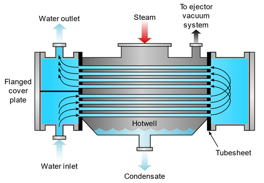
Inside the condenser, thousands of cooling water tubes create a large heat transfer surface. Exhaust steam flows around these tubes while cooling water circulates through them, causing the steam to condense on the tube surfaces. The condensed water then drips down and collects in the hotwell section below.
Surface Condenser: Water in the Tube
Key function: Efficiently converts low-pressure exhaust steam back to liquid condensate while maintaining vacuum conditions that improve overall cycle efficiency.
2. Hotwell: The Collection Basin
Click to learn how hotwell acts as a basin
The hotwell acts as the collection reservoir located at the bottom of the surface condenser. This critical component stores the newly formed condensate at saturation temperature, providing a buffer between condensate formation and extraction.
The hotwell maintains proper water level to ensure condensate extraction pumps have adequate suction head while preventing air ingress that could damage downstream equipment. It also serves as a mixing point where condensate from various sources combines before being pumped back to the cycle.
Key function: Provides condensate storage, maintains proper water inventory, and ensures reliable suction conditions for extraction pumps.
3. Condensate Extraction Pumps (CEPs): The Movers
Click to learn how CEPs handle the demanding fluids
Condensate extraction pumps are the workhorses that move hot condensate from the low-pressure hotwell back to higher-pressure sections of the steam cycle. These specialized pumps must handle high-temperature water (often near boiling point) while maintaining reliable operation.
CEPs typically operate in multiple stages to gradually increase pressure, preventing cavitation and ensuring smooth flow. They’re designed with features like minimum flow bypasses and special impeller materials to handle the demanding conditions of hot condensate service.
Key function: Reliably transport hot condensate from collection points back to the boiler feedwater system, overcoming pressure and elevation differences.
4. Low-Pressure Heaters (LP Heaters): A Gentle Preheat
Click to learn how LP Heaters work as an efficiency booster
Low pressure heaters represent the first stage of feedwater heating in the regenerative cycle. These heat exchangers use extraction steam from turbine intermediate stages to preheat the condensate before it reaches higher-pressure heaters.
LP heaters improve overall cycle efficiency by recovering heat that would otherwise be lost in the condenser. They typically operate with extraction steam at pressures between 15-50 psia, raising condensate temperature by 40-80°F depending on system design.
Key function: Capture waste heat from turbine extraction steam to preheat condensate, improving overall thermal efficiency and reducing fuel consumption.
How Do These Components Work Together?
These four components form an integrated system where each element depends on the others. The surface condenser creates the condensate, the hotwell stores and manages it, the CEPs move it forward in the cycle, and the LP heaters begin the process of heat recovery that makes the entire system economically viable.
When properly sized and maintained, these components work in harmony to maximize condensate recovery, minimize energy waste, and ensure reliable water return to the boiler system.
Condenser Operation Basics
The surface condenser is where the magic happens—transforming waste steam back into valuable condensate through efficient heat exchange and vacuum operation. Understanding these two fundamental principles is key to optimizing condensate recovery performance.
1. Heat Exchange with Cooling Water
I. The Heat Transfer Process
Inside the condenser, thousands of thin-walled tubes carry cooling water while exhaust steam flows around the outside of these tubes. This design maximizes heat transfer surface area while keeping cooling water completely separate from the condensate—preserving the purity of water returning to the boiler.
As steam contacts the cool tube surfaces, it releases approximately 970 BTU per pound of latent heat energy. This massive heat release causes the steam to condense into water droplets that flow down the tubes and collect in the hotwell below.
II. Cooling Water Circuit Efficiency
The effectiveness of heat exchange depends heavily on cooling water temperature and flow rate. Cooler inlet water temperature allows for more efficient condensation and better vacuum conditions. Typical cooling water temperature rise across the condenser ranges from 15-25°F, with inlet temperatures ideally kept below 85°F for optimal performance.
Higher cooling water flow rates improve heat transfer but increase pumping costs. The key is finding the optimal balance between heat transfer efficiency and operating costs, typically achieved through careful control of cooling water flow based on condenser performance requirements.
2. Role of Vacuum and Ejectors
I. Why Vacuum Matters
Lower condensing temperature: At atmospheric pressure, steam condenses at 212°F. Under vacuum (say, 2 inches Hg absolute), steam condenses at only 126°F. This lower temperature differential between steam and cooling water dramatically improves heat transfer efficiency.
Improved turbine performance: Vacuum at the turbine exhaust allows for greater pressure drop across the turbine, extracting more work from each pound of steam and improving overall power plant efficiency.
Enhanced condensation rate: Lower pressure reduces the energy barrier for steam-to-water phase change, allowing faster and more complete condensation with the same cooling water supply.
The Energy Barrier Concept: How Pressure Affects This Barrier
At Higher Pressure (like atmospheric):
Steam molecules are packed more tightly together
They have higher kinetic energy due to the pressure
More of this kinetic energy must be removed before molecules can “settle down” into the more organized liquid state
The condensation process requires removing more energy per molecule
At Lower Pressure (vacuum conditions):
Steam molecules are more spread out with less pressure forcing them together
They naturally have lower kinetic energy
Less energy needs to be removed for molecules to transition to liquid state
The phase change happens more readily with less heat removal required
Reduced energy barrier translates to: Steam turns to water more quickly, higher percentage of steam condenses, less cooling water needed to achieve the same condensation, you don’t need as cold of cooling water to get effective condensation.
II. Steam Jet Ejectors: The Vacuum Creators
A steam jet ejector is essentially a specialized nozzle system with no moving parts. These devices create and maintain condenser vacuum. It uses high-pressure motive steam to create suction that removes non-condensable gases (air, CO₂, etc.) from the condenser, maintaining the vacuum conditions we need.
Primary ejectors handle the bulk of gas removal, typically maintaining condenser pressure between 1-4 inches Hg absolute. They operate continuously during normal operation, using relatively small amounts of high-pressure steam to remove large volumes of low-pressure gases.
Auxiliary ejectors provide backup capacity and handle startup/shutdown conditions when gas loads are highest. During initial startup, these ejectors work overtime to establish vacuum conditions from atmospheric pressure.
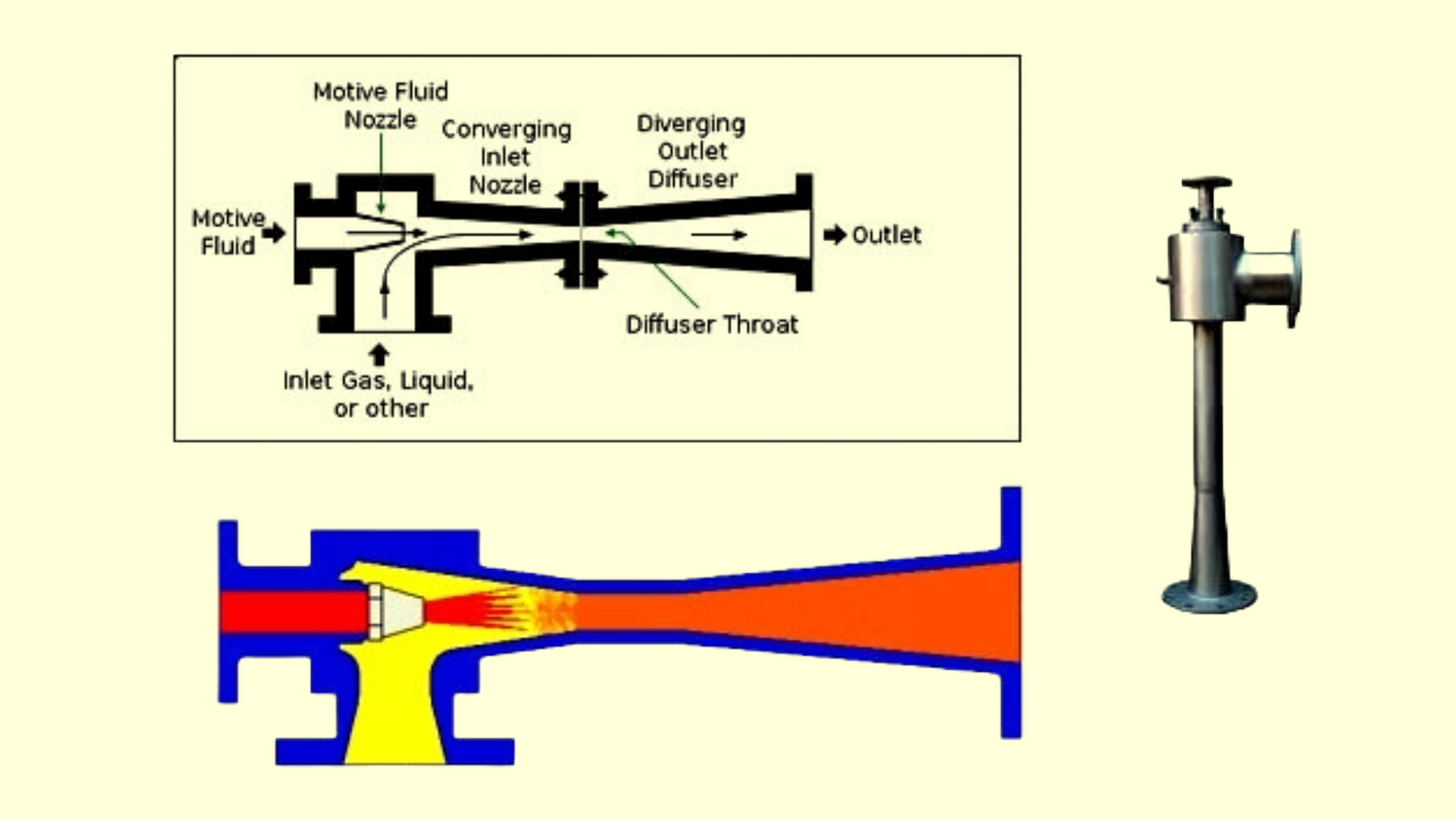
What is a Steam Jet Ejector? : The Basic Operating Principle
Steam jet ejectors work on the principle of venturi effect—same as a garden hose nozzle or a carburetor. Here’s the step-by-step process:
High-pressure motive steam (typically 150-600 psig) enters the ejector through a convergent-divergent nozzle
As this steam expands through the nozzle, it accelerates to very high velocity (often supersonic speeds)
This high-velocity steam jet creates a low-pressure zone around it (Venturi effect)
The low pressure entrains (sucks in) gases from the condenser
The mixed stream of motive steam and entrained gases flows into a diffuser section
In the diffuser, velocity decreases and pressure recovers slightly, but the entrained gases are already carried away—serving the purpose.
Steam jet ejector working principle
Common Problems and Field Symptoms
1. Air Ingress
I. What Happens
Air leaking into the condenser is one of the most insidious problems in condensate systems because it’s invisible but devastating to performance. Since the condenser operates under vacuum, atmospheric air constantly tries to enter through any available path.
II. Field Symptoms
Rising condenser pressure despite normal cooling water flow and temperature. If your vacuum gauge shows deteriorating conditions (higher absolute pressure readings), air ingress is often the culprit.
Poor heat transfer efficiency becomes apparent when cooling water outlet temperature drops while steam flow remains constant. Air acts as an insulating blanket around heat transfer tubes, dramatically reducing condensation rates.
Increased ejector steam consumption as the steam jet ejectors work overtime trying to remove the excess air. You’ll see higher motive steam flow to ejectors without corresponding improvement in vacuum.
Erratic condenser performance with vacuum levels that fluctuate unexpectedly or fail to maintain steady readings during consistent operating conditions.
III. Why It Happens
Deteriorated gaskets on manways, instrument connections, or expansion joints
Cracked welds or corrosion holes in condenser shells
Leaking valve stems on vent and drain valves
Improperly sealed penetrations for instrumentation or piping
2. CEP Cavitation
I. What Happens
Cavitation occurs when the pressure at the pump suction drops below the vapor pressure of the condensate, forming vapor bubbles that collapse violently inside the pump..
II. Field Symptoms
Characteristic noise that sounds like gravel or marbles rattling inside the pump casing. This distinctive sound is often the first sign operators notice.
Erratic pump discharge pressure with readings that fluctuate wildly instead of maintaining steady values. The pump struggles to develop consistent head due to vapor bubble formation.
Excessive vibration as the pump shaft becomes unbalanced from cavitation damage and vapor bubble collapse. Vibration monitoring will show elevated readings.
Declining pump performance with reduced flow rates even though motor amperage may increase as the pump works harder against cavitation conditions.
III. Why It Happens
Insufficient NPSH (Net Positive Suction Head) when hotwell level drops too low or suction piping creates excessive pressure drop
High condensate temperature near saturation point, making vapor formation easier
Pump oversizing where the pump tries to move more flow than suction conditions support
Blocked or partially closed suction valves creating artificial pressure drop
3. High Hotwell Level
I. What Happens
When condensate builds up faster than it’s being extracted, the hotwell level rises excessively.
II. Field Symptoms
Condenser flooding where liquid level rises into the tube bundle area, drastically reducing effective heat transfer surface and destroying condenser performance.
CEP flow instability as pumps experience changing suction conditions or begin handling mixed liquid/vapor flow instead of steady condensate.
Automatic pump trips as high-level switches activate to protect equipment, but this creates its own problems with condensate backup.
Overflow at drains or relief valves with hot condensate spilling to the drain system, representing direct loss of valuable treated water and heat energy.
III. Why It Happens
CEP capacity insufficient for the condensate load, often during peak steam demand periods
Downstream flow restrictions in the condensate return system backing up flow
Control valve failures on level control systems, causing pumps to operate improperly
Steam load variations overwhelming the designed capacity of extraction pumps
Instrument failures on level measurement systems, preventing proper automatic control
Control Strategies
Effective condensate system control isn’t just about maintaining water levels—it’s about creating a coordinated system that automatically responds to changing conditions while protecting expensive equipment and maximizing recovery efficiency. Two critical control strategies form the backbone of reliable condensate operation.
1. Hotwell Level Control
The hotwell level must be kept within a narrow range—too low and the CEPs may cavitate; too high and the system may overflow or trip.
Three-Element Control Strategy
Level Signal (Primary): Direct measurement of hotwell water level provides the main feedback for control action. Modern systems use multiple level transmitters for redundancy and accuracy across the full operating range.
Condensate Flow (Secondary): Measuring incoming condensate flow allows the control system to anticipate level changes before they occur, providing feedforward control that prevents large level swings.
Pump Speed/Flow (Corrective): Variable frequency drives (VFDs) on condensate extraction pumps provide the control output, automatically adjusting pump capacity to match condensate generation rates.
2. Interlocks with Feedwater System
The condensate system must stay in sync with the feedwater system, especially during transients like load changes, startup, or shutdown.
Rising steam consumption = ejector fouling or air ingress
Declining vacuum = system leaks or cooling issues
Erratic readings = control problems or equipment wear
2. Leak Detection
Primary Detection Methods:
Bubble testing during shutdowns (soapy water)
Helium leak detection for operating systems
Ultrasonic detection for valve stems and small cracks
High-Priority Leak Locations:
Expansion joints and flexible connections
Manway door gaskets
Instrument penetrations and isolation valves
Vent and drain valve stems
3. Hotwell Level Tuning Tips
Controller Setup:
Start with conservative PID settings (P=1-3, I=5-15 min, D=0)
Use feedforward control with condensate flow
Implement anti-windup protection
Performance Targets:
Maintain level within ±10% of setpoint
Minimize pump cycling during steady conditions
Prevent cavitation during transient events
Conclusion: The Unsung Hero of Steam Cycle Efficiency
While boilers and turbines grab the spotlight in steam system discussions, the condensate system quietly does the heavy lifting that makes everything else possible. It’s the unsung hero that transforms what would be waste into valuable resources, closing the loop that defines efficient steam cycle operation.
Every day, your condensate system makes thousands of decisions automatically—removing air to maintain vacuum, adjusting pump speeds to control levels, and recovering heat energy that would otherwise vanish into the atmosphere. When it works properly, nobody notices. When it fails, everyone feels the impact through higher fuel bills, makeup water costs, and equipment problems.
The condensate system may be the unsung hero of steam cycle efficiency, but its impact on your bottom line sings loud and clear in every monthly utility bill. Give it the attention it deserves, and it will reward you with years of reliable, efficient operation that captures every possible drop of value from your steam investment.


3 Comments
Comments are closed.