Understanding Lube Oil Systems: A Power Plant Engineer’s Guide
Hey Future Power Engineers!
ALARMS STARTED SCREAMING!– your main lube oil pump had failed, and the backup hadn’t started automatically. In those terrifying 30 seconds before the emergency DC pump kicked in, you would realize something profound: what keeps the massive turbines and generators in power plants spinning smoothly hour after hour, the answer often boils down to something simple—lubricating oil.
A lube oil system is the lifeblood of rotating machinery, providing essential lubrication, cooling, and protection to components that operate under extreme conditions. It reduces friction, removes heat, prevents wear, and helps equipment last for years. Whether it’s a steam turbine, gas turbine, or generator, if the lube oil system fails—even for a few seconds—the entire unit could suffer catastrophic damage.
In this comprehensive guide, we’ll explore every aspect of lube oil systems – from basic principles to advanced applications. You’ll learn about essential components, operational principles, maintenance requirements, and safety considerations. We’ll conclude with a detailed real-world example from a GE F-class gas turbine, demonstrating how these principles apply in one of the most demanding industrial environments.
By the end of this article, you’ll understand why experienced engineers always say: “Take care of your lube oil system, and it’ll take care of your equipment.”
What is a Lube Oil System?
A lube oil system is a closed-loop mechanical system designed to continuously circulate lubricating oil to various components of rotating machinery. The primary purpose is to create a thin film of oil between moving surfaces, reducing friction, removing heat, and preventing metal-to-metal contact that could cause catastrophic failure.
Key Functions
- Friction Fighter: It creates a microscopic oil film between metal surfaces. Without this film, metal parts would weld together in seconds at the speeds and loads we deal with in power generation. We’re talking about turbine shafts spinning at 3,000 RPM carrying massive loads!
- Heat Removal Expert: Your turbine bearings can generate incredible amounts of heat. The oil absorbs this heat and carries it away to coolers. I’ve seen bearing temperatures hit 200°F+ when cooling systems fail – that’s when things get scary fast.
- Contamination Controller: As equipment runs, it generates tiny metal particles from normal wear. The oil picks up these particles and carries them to filters before they can cause damage. It’s like having a cleaning crew working 24/7.
- Corrosion Prevention Specialist: Modern oils contain special additives that coat metal surfaces, preventing rust and corrosion during shutdowns when protective oil films might drain away.
>>> See lubrication standards here.
Types of Lube Oil Systems
- Splash Lubrication: The simplest form where rotating components dip into an oil bath. Common in small engines and gearboxes, but limited in cooling capacity and unsuitable for high-speed applications.
- Pressure-Fed Systems: Oil is pumped under pressure to specific lubrication points. This allows precise oil delivery and is suitable for medium-speed applications with moderate loads.
- Circulating Systems: This is the big league – what you’ll find on your main turbines and generators. It’s the most sophisticated type, featuring continuous oil circulation through pumps, filters, coolers, and distribution networks. We’ll dive deep into these since they’re your bread and butter in power generation.
- Mist Lubrication: Oil is atomized and carried by air to lubrication points. Used in special applications where conventional wet lubrication isn’t practical.
Essential Components of Lube Oil Systems
Oil Reservoir/Tank: Your System’s Foundation
The oil reservoir serves as the system’s heart, storing the oil inventory and providing space for thermal expansion, air separation, and contaminant settling. Tank design must consider several factors: adequate capacity for system volume plus expansion, proper venting to prevent pressure buildup, baffles to reduce oil turbulence, and immersion heaters– usually around 10-20 kW worth for cold weather starting.
Capacity calculations typically include the system’s circulating volume plus 20-30% for expansion and makeup. For critical applications, tanks often feature redundant level measurement, temperature monitoring, and emergency makeup connections. The tank’s interior surface requires compatible coatings to prevent contamination, while external insulation may be necessary in cold climates.
Straight from the Field: Always check the oil level first thing during your rounds.
Pumps: The Muscle of the Operation
Pumps provide the driving force for oil circulation, and redundancy is critical for continuous operation.
Main AC Pumps: Main circulation pumps are typically AC motor-driven centrifugal units sized for normal operating flow and pressure requirements. Usually two identical centrifugal pumps, each capable of handling the full system flow while maintaining adequate pressure at the furthest lubrication point.
Straight from the Field: pump cavitation sounds like marbles in a blender. If you ever hear that sound, shut down immediately and check your suction conditions.
Emergency DC Pump: This is your insurance policy. When AC power fails (and it will), this DC-powered pump keeps oil flowing during the critical coast-down period. It’s not sized for normal operation – just enough to prevent bearing damage while the turbine spins down.
Seal Oil Pumps: For hydrogen-cooled generators, you need separate seal oil pumps to maintain pressure seals. These prevent hydrogen leakage and are absolutely critical for safety.
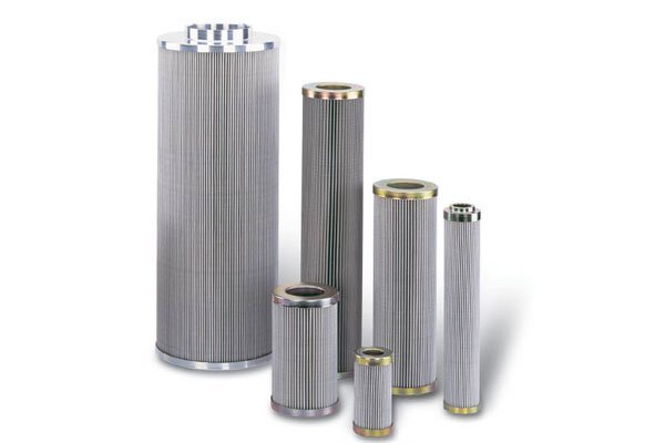
Filtration: Your First Line of Defense
Filtration systems remove contaminants that could cause wear, deposits, or system plugging. Primary filters catch the big stuff (25-40 microns), while secondary filters polish the oil down to 3-10 microns. For perspective, human hair is about 75 microns thick, so we’re talking about incredibly fine filtration.
We typically run dual filter systems – you can switch between them without shutting down the unit. Watch your differential pressure gauges religiously. It provides early warning of filter loading, enabling proactive maintenance scheduling. When filter ΔP hits the alarm setpoint (usually 15-25 PSI differential), it’s time to switch to the standby filter and change elements.
Filter housing design must accommodate thermal expansion, provide bypass capability for emergency operation, and allow safe element replacement. Advanced systems may include magnetic separators for ferrous particles, water separators for moisture removal, and specialty filters for specific contaminants like acids or oxidation products.
Heat Exchangers: Temperature Control Masters
Temperature control is crucial for maintaining proper oil viscosity and preventing thermal degradation. Too hot, and the oil breaks down chemically. Too cold, and it becomes thick as molasses. Heat exchangers remove heat absorbed during lubrication, maintaining oil temperature within acceptable limits.
Most systems use shell-and-tube heat exchangers with oil on the shell side and cooling water on the tube side. Like filters, these are usually dual systems for redundancy to facilitate continuous operation. The key is keeping cooling water flow consistent and monitoring both inlet and outlet temperatures.
Straight from the Field: If your oil temperature starts climbing despite normal cooling water flow, check for fouling in the heat exchanger. Scale buildup is a common culprit that reduces heat transfer efficiency.
Instrumentation: Your Eyes and Ears
Modern lube oil systems are loaded with sensors, and for good reason. Key measurements include:
- Pressure: Tank pressure, pump discharge pressure, bearing supply pressure, filter differential pressure
- Temperature: Tank temperature, header temperature, bearing supply and drain temperatures
- Flow: Total system flow and individual component flows
- Level: Tank oil level with high, normal, and low alarms
Learn to read these instruments like a story. Rising bearing drain temperature might indicate bearing problems. Increasing filter differential pressure means contamination loading. Fluctuating pump discharge pressure could signal cavitation or wear.
Pressure Regulation: Maintain Your BP
Pressure regulating valves maintain consistent oil pressure to lubricated components regardless of flow variations or system changes. These valves automatically adjust to maintain set pressure while bypassing excess flow back to the reservoir.
System pressure requirements depend on lubricated components, with higher pressures needed for journal bearings versus splash-lubricated gears. Safety relief valves protect against overpressure conditions, while pressure switches provide alarm and trip functions for low-pressure situations.
How Lube Oil Systems Work Together
Understanding the operational flow of a lube oil system reveals the elegant simplicity underlying its complex design.
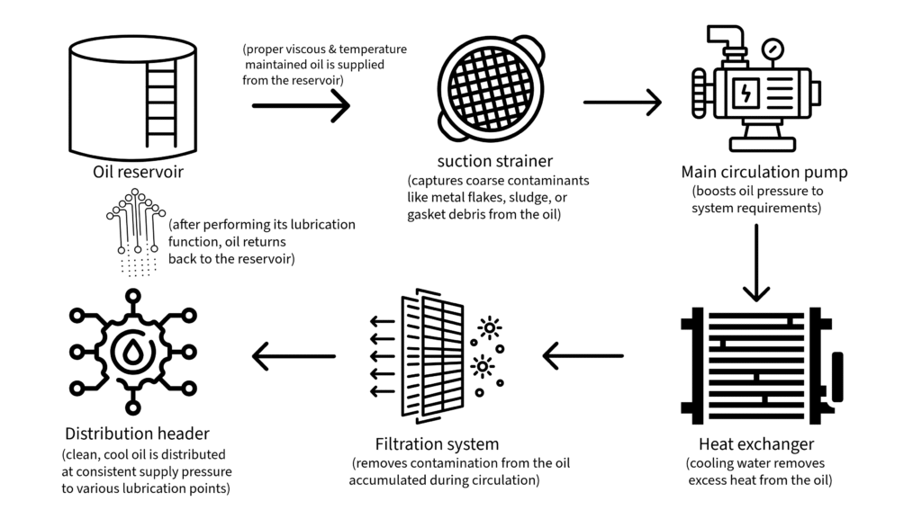
- The process begins in the oil reservoir, where oil is maintained at proper temperature and level. During startup, immersion heaters ensure oil viscosity is suitable for pumping and circulation.
- Oil flows from the reservoir through suction strainers into the main circulation pumps. These pumps, typically redundant centrifugal units, boost oil pressure to system requirements.
- From the pump discharge, oil flows through heat exchangers where cooling water removes excess heat, maintaining optimal temperature for lubrication system effectiveness.
- After cooling, oil passes through filtration systems that remove contamination accumulated during circulation.
- Clean, cool oil then enters the distribution header where pressure regulating valves maintain consistent supply pressure regardless of flow variations.
- From the main header, oil branches to various lubrication points: journal bearings receive pressurized oil that forms a hydrodynamic film supporting rotating shafts; thrust bearings receive oil to handle axial loads; gear teeth receive spray lubrication for wear protection; and hydraulic systems receive filtered oil for actuator operation.
- After performing its lubrication function, oil drains by gravity back to the reservoir, completing the circulation loop. During this return journey, oil carries away heat, wear particles, and other contaminants that will be removed during the next circulation cycle.
The system operates under automatic control with continuous monitoring. Pressure switches detect low pressure conditions, automatically starting standby pumps or initiating emergency procedures. Temperature monitoring ensures oil remains within acceptable limits, while level switches prevent operation with inadequate oil inventory.
Emergency operation modes activate during power failures or major component malfunctions. DC emergency pumps provide continued lubrication during coast-down periods, while accumulator systems may provide short-term pressurized oil supply. These emergency systems are sized to prevent bearing damage during abnormal conditions.
Choosing the Right Oil
Oil selection might seem straightforward, but it’s actually quite complex. In power generation, we typically use high-quality turbine oils meeting strict specifications.
Mineral vs. Synthetic
Mineral oils are still the workhorses of power generation. They’re cost-effective, widely available, and perform well in most applications. Modern mineral turbine oils are highly refined with excellent additive packages.
Synthetic oils offer superior performance but at 3-5 times the cost. They’re worth it in extreme temperature applications or where extended drain intervals justify the extra expense. I’ve seen synthetic oils run 5+ years in gas turbines versus 2-3 years for mineral oils.
Key Properties to Understand
Viscosity: This is how thick or thin the oil is. Too thick, and pumps work harder and heat generation increases. Too thin, and you lose the protective film between metal surfaces. Most power plant applications use ISO VG 32 or 46 oils.
Viscosity Index (VI): Higher VI means viscosity changes less with temperature. Important for equipment that operates across wide temperature ranges.
Oxidation Stability: How well the oil resists chemical breakdown at high temperatures. Poor oxidation stability leads to sludge formation and acid production.
Additives That Matter
Modern turbine oils contain sophisticated additive packages:
- Antioxidants: Prevent oil degradation
- Anti-foam agents: Prevent foam formation that causes cavitation and poor lubrication
- Corrosion inhibitors: Protect metal surfaces during operation and shutdowns
- Metal deactivators: Neutralize catalytic metals that accelerate oil degradation
>>> See more about oil specifications here.
Maintenance: Your Daily Bread
Proper maintenance separates good engineers from great ones. Here’s what I’ve learned working in the real world:
Oil Analysis: Your Crystal Ball
Regular oil analysis is like getting a blood test for your equipment. I recommend monthly sampling for critical units, quarterly for less critical equipment. Key tests include:
- Viscosity: Indicates oil degradation or contamination
- Acid number: Shows oxidation byproducts
- Water content: Water causes bearing corrosion and oil degradation
- Particle count: Indicates contamination levels and filter effectiveness
- Metals analysis: Reveals wear patterns in equipment
Learn to interpret trends, not just individual results. A gradual increase in iron content might indicate normal bearing wear, while a sudden spike suggests a problem requiring immediate attention.
Filter Management
Change filters based on differential pressure, not time schedules. Most systems alarm at 15-25 PSI differential. Here’s my procedure:
- Start standby filter circulation and verify oil flow in sight glass
- Switch three-way valve to put standby filter in service
- Isolate and drain loaded filter
- Change elements and inspect housing
- Fill and vent before returning to standby status
Pump Care
Centrifugal pumps are generally reliable, but watch for:
- Cavitation: That marble-in-a-blender sound I mentioned
- Bearing wear: Increasing vibration or temperature
- Seal leakage: External oil leaks or oil in seal water
Emergency pumps need regular testing – monthly is typical. Don’t just start them; verify they develop proper pressure and flow.
Heat Exchanger Maintenance
Keep an eye on approach temperatures. If the oil outlet temperature starts creeping up despite normal cooling water flow, you’ve got fouling. Most heat exchangers need cleaning annually or biannually.
Water-side cleaning removes scale and biological growth, while oil-side cleaning removes oxidation deposits and sludge.
Troubleshooting Like a Pro
After years of experiences, I’ve seen most problems multiple times. Here are the common issues and how to handle them:
Low Oil Pressure
This is a big one that’ll wake you up at night. Causes include:
- Pump problems: Cavitation, wear, or mechanical failure
- System leakage: Check for external leaks or internal bypassing
- Filter plugging: High differential pressure restricts flow
- Oil viscosity issues: Wrong oil or temperature problems
Start with the basics: verify oil level, check pump operation, look for obvious leaks.
High Oil Temperature
Usually indicates heat exchanger problems:
- Fouling: Reduced heat transfer efficiency
- Cooling water issues: Low flow, high inlet temperature, or air binding
- Excessive heat generation: Could indicate bearing problems
Check cooling water flow and temperature first – it’s the most common cause.
Oil Contamination
Shows up in oil analysis as high particle counts, water content, or unusual chemistry:
- External contamination: Poor sealing, inadequate filtration
- Internal generation: Equipment wear or oil degradation
- Cross-contamination: Mixing incompatible oils
Identify the source before treating the symptoms. Better filtration won’t help if you have a major seal leak.
Pump Vibration
Usually indicates:
- Cavitation: Check suction conditions
- Bearing wear: Monitor vibration trends
- Misalignment: Often occurs after maintenance
- Resonance: Operating at critical frequency
Use vibration analysis to pinpoint the problem. Don’t ignore increasing vibration – it always gets worse, never better.
Real-World Example: GE F-Class Gas Turbine System
Let me share details from a system I know intimately – the lube oil system on a GE F-class gas turbine. This is a perfect example of how all these principles come together in a critical power generation application.
Major System Components
- LO (Lube Oil) reservoir
- Two centrifugal main LO pumps, each driven by an AC electrical motor (88QA- 1/2).
- Emergency LO pump, driven by a DC motor (88QE-1).
- Main seal oil pump, driven by an AC motor (88QS-1).
- Emergency seal oil pump, driven by a DC motor (88ES-1).
- Dual full flow LO heat exchangers (LOHX-1/2).
- Dual full flow LO filters (LF3-1/2).
- LO header pressure regulator valve (VPR2-1).
- Mist eliminators with redundant blowers, driven by AC motors (88QV-1A/B).
- Pressure protection switches and/or transmitters.
- Tank temperature thermocouples for pump start permissive and immersion heater control.
- LO header thermocouples.
- LO drain thermocouples.
Working Procedure of the Lube Oil System
1. Oil is stored in the main reservoir
- The tank is internally coated to resist oil corrosion.
- It serves as the base for mounting components like pumps, filters, and heat exchangers.
2. An AC motor-driven (88QA-1/2) main pump draws oil from the reservoir
- Two main pumps are available (lead and lag); only one runs at a time.
- Pump selection is done manually before startup via the turbine control system.
- A check valve on each pump discharge line prevents backflow into idle pumps.
3. Oil flows into a common discharge header just downstream of the main pumps
- A pressure transmitter here monitors the line pressure.
- If pressure drops, an alarm is triggered and the lag pump starts automatically.
4. Oil is directed through a selected heat exchanger (LOHX-1/2) and filter (LF3-1/2)
- A three-way transfer valve (VA32-1) selects one of two heat exchanger–filter pairs.
- Only one heat exchanger and filter pair is active at any time.
- Heat exchangers cool the oil to maintain bearing header temperature ≤ 160°F (71°C).
- Filters remove particulates from the oil; differential pressure is monitored for clogging.
5. Cooled and filtered oil reaches the lube oil (LO) header
- This is the main supply line for oil distribution.
- Pressure is regulated downstream using a pressure regulating valve (VPR2-1).
6. Oil is distributed from the LO header to critical components:
- Turbine and generator bearings
- Turning gear bearings
- Generator seal oil system
- Hydraulic and lift oil systems
7. During standby, immersion heaters maintain oil temperature in the reservoir
- Prevents high viscosity that could delay safe startup
- Thermocouples monitor temperature and trigger low-temp alarms if needed
8. If oil pressure drops below safe limits (due to pump failure or power loss):
- A DC emergency pump (driven by 88QE-1 motor) is automatically started
- It provides oil for coast-down and post-trip cooling
- If bearing metal temperature is high (>250°F), it may run continuously
The Hydraulic and Lift Oil Connection: More Than Just Lubrication
Here’s something that confuses many young engineers – why does our “lube oil system” have lines going to hydraulic pumps? The answer reveals the elegant efficiency of modern power plant design.
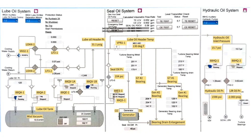
Your lube oil system actually feeds three distinct subsystems, each with different pressure requirements:
I. The Three-Zone System Breakdown
Lube Oil Zone: Provides low-pressure lubrication (60-80 PSI) to bearings, gears, and rotating equipment. This is your basic lubrication function we’ve been discussing.
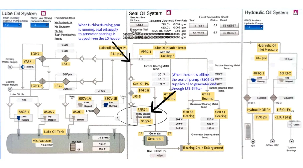
Seal Oil Zone: Supplies medium-pressure oil (typically 100-150 PSI) to generator hydrogen seals. When the turbine/turning gear is running, the main lube oil pumps (driven by 88QA-1/2 motors) handle the hydrogen sealing. Seal oil supply to generator bearings is tapped from the LO header (post-filter, pre-VPR2-1). When the unit is offline, dedicated seal oil pump (driven by 88QS-1) takes over to maintain generator seal integrity.
- Under offline condition, the seal oil pump (driven by 88QS-1) supplies oil. Otherwise, seal oil supply to generator bearings is tapped from the LO header. LO header pressure is maintained by main lube oil pumps (driven by 88QA-1/2 motors).
- If AC power fails, an emergency DC pump (driven by 88ES-1) takes over for sealing purpose
- Seal oil has a dedicated filter (LF3-5) and high differential pressure monitoring
Hydraulic Oil Zone: Takes clean, filtered oil from the lube oil header and boosts it to very high pressure (1500-2000+ PSI). The hydraulic oil system is primarily responsible for actuating and controlling key components in the turbine, such as:
- Inlet Guide Vanes (IGVs) for air flow control
- Gas Control Valves (GCVs) and Load Bypass Valves (LBVs) for fuel flow and pressure regulation
These components must respond quickly and precisely to control commands—and that’s where hydraulic pressure comes in.
II. Why the Hydraulic System Needs Such High Pressure
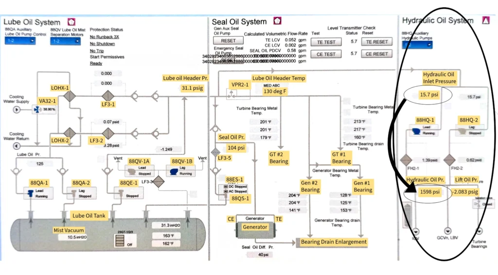
You’re absolutely right – the hydraulic oil pump takes that 15.7 PSI supply pressure and cranks it up to 1598 PSI. Here’s why this massive pressure boost is essential:
Valve Actuator Requirements: Your turbine inlet guide vanes, gas control valves, and extraction valves are massive – some with valve discs 12+ inches in diameter fighting gas pressures of 1000+ PSI. To move these valves quickly and reliably, you need hydraulic actuators with enough force to overcome:
- Gas pressure acting on the valve disc
- Valve packing friction
- Spring forces in the actuator
- Dynamic forces during fast opening/closing
Control Response Speed: In an emergency trip, these valves must close in seconds, not minutes. High hydraulic pressure provides the muscle needed for rapid, reliable operation.
System Reliability: Higher pressure means smaller actuators for the same force output, and more positive valve positioning. There’s no room for “maybe” when you need to shut steam valves during a turbine trip.
III. Understanding Lift Oil Pressure
This is where it gets interesting, and your pressure readings tell the whole story:
During Normal Operation (-2.083 PSI): That negative pressure isn’t really “lift oil” working – it’s actually indicating that the turbine rotor is supported by normal journal bearing oil films. The lift oil system is essentially inactive, hence the slightly negative reading (probably just measurement offset or slight vacuum).
During Turning Gear Operation (2700+ PSI): Now the lift oil system is doing its job! Here’s what’s happening:
When the turbine is offline, the rotor weighs several tons and would create flat spots on the bearing surfaces if it just sat there. The lift oil system uses extremely high pressure oil (2500-3000 PSI) injected directly under the rotor to literally “lift” it off the bearing surfaces.
This high-pressure oil creates a pressurized oil film that supports the full weight of the rotor, allowing the turning gear to rotate it slowly (about 3-6 RPM) without any metal-to-metal contact.
IV. How the Process Goes
Here’s the flow path that makes it all work:
- Clean Oil Supply: Filtered oil from the main lube oil header (after filters, at system pressure) feeds the hydraulic pump suction
- Pressure Boost: The hydraulic pump (driven by 88HQ-1/2 motors) takes this clean, low-pressure oil and boosts it to system hydraulic pressure (pressure raised from 15.7 psi to 1598 psi in this case)
- Accumulator Storage: High-pressure accumulators store hydraulic oil under pressure for instant response
- Distribution: High-pressure oil flows to valve actuators throughout the plant
- Return Path: Used hydraulic oil returns to the main lube oil tank at low pressure
For lift oil, a separate high-pressure pump (or sometimes the same hydraulic pump with different pressure settings; such as this case) provides the extreme pressures needed to lift the rotor weight.
V. Why This Design Makes Sense
Using the lube oil system as the source for hydraulic oil is brilliant engineering:
- Single Oil Type: One oil inventory serves multiple functions
- Shared Filtration: Hydraulic components get the same clean oil as critical bearings
- Integrated Monitoring: Oil condition monitoring covers all systems
- Simplified Maintenance: One oil analysis program, one oil change procedure
- Cost Efficiency: Shared infrastructure reduces capital and operating costs
The beauty is that each subsystem gets exactly what it needs: low-pressure lubrication for bearings, medium-pressure sealing for generators, and high-pressure power for valve actuation – all from the same carefully maintained oil supply.
What I’ve Learned
Working with this system taught me several key lessons:
- Redundancy works: I’ve never seen a unit trip due to lube oil system failure when properly maintained
- Keep it simple: Complex control logic often fails; simple, robust designs don’t
- Monitor trends: Gradual changes often indicate developing problems
- Emergency systems need testing: Monthly testing of the DC pump prevented several potential problems
- Oil analysis pays: Regular analysis caught bearing problems early, saving major repairs
The sophistication of this system demonstrates how critical lubrication system is in modern power generation. Every component has backup, every critical parameter is monitored, and the control system can respond to problems faster than human operators.
Safety: Don’t Learn This the Hard Way
I’ve seen too many close calls over the years. Lube oil systems demand respect – they operate under pressure with flammable fluids at elevated temperatures.
Fire Prevention
Oil mist and vapors create explosive atmospheres. Key precautions:
- Maintain proper ventilation around equipment
- Control ignition sources during maintenance
- Use appropriate fire suppression systems (foam or CO2 for oil fires)
- Keep hot work permits current and detailed
I once saw a small oil leak create a flash fire when it contacted a hot surface. Nobody was hurt, but it could have been catastrophic.
Personal Protection
Hot oil burns are nasty and heal slowly. Always wear:
- Chemical-resistant gloves when handling oil
- Safety glasses or face shields near pressurized systems
- Long sleeves and pants to prevent contact burns
- Slip-resistant footwear in areas where spills occur
Pressure Safety
Pressurized oil injection injuries are serious business. Oil under pressure can penetrate skin and cause internal damage. Never check for leaks with your hands – use cardboard or other detection methods.
Always follow lockout/tagout procedures before opening pressurized systems.
Environmental Responsibility
Oil spills are environmental disasters and regulatory nightmares. Prevention includes:
- Secondary containment around all equipment
- Regular inspection of piping and connections
- Immediate cleanup of even small spills
- Proper disposal of used oil and filters
The regulations are strict and penalties severe. It’s much easier to prevent spills than clean them up.
Wrapping Up: Your Path Forward
Here’s what I want you to remember as you build your career in power generation:
Master the Basics: Understanding how oil lubricates, how pumps work, and how filters function will serve you throughout your career. Don’t skip these fundamentals.
Think Systems: Everything is connected. A filter problem affects pump operation, which impacts bearing lubrication, which influences equipment reliability. Learn to see the big picture.
Develop Diagnostic Skills: Learn to interpret oil analysis, understand vibration patterns, and recognize early warning signs. These skills separate good engineers from great ones.
Respect the Hazards: Lube oil systems can hurt you if you’re careless. Follow safety procedures religiously and never take shortcuts.
Embrace Technology: New monitoring and diagnostic tools can make you more effective, but they don’t replace fundamental understanding.
Learn from Experience: Every problem teaches you something. Document what you learn and share it with others.
The lube oil system might seem like just auxiliary equipment, but it’s actually the foundation that everything else depends on. Master these systems, and you’ll have the confidence to handle any lubrication system challenge in your power plant career.
Keep learning, stay curious, and never stop asking “why” – that’s what makes a great power plant engineer.
~Rotormind