How Gas Turbine Starts Using Rotating Magnetic Fields: Complete Guide
Author |Rotormind
The Beautiful Paradox of Power Generation
You’re standing in front of a massive gas turbine power plant. This mechanical giant needs to accelerate from complete stillness to over 3,000 RPM before it can even begin to sustain itself on fuel combustion. How do you even begin to spin something that massive?
Here’s where it gets fascinating, and frankly, a bit mind-bending when you first encounter it: that same generator that will soon be producing megawatts of electrical power for the grid is– during these crucial startup moments– actually consuming electrical power and working as a motor helping the giant turbine rotate from stillness. Yes, you read that right – the generator temporarily becomes a motor.
We’ll comprehensively understand this starting process by explaining a control system diagram which represents the LS2100e Static Start System. It is essentially the “electrical muscle” that gets our massive gas turbine spinning. Don’t let the term “static” fool you; while the electronics have no moving parts, they’re creating something incredibly dynamic: a rotating magnetic field that can coax multiple tons of steel into smooth, controlled rotation.
In the sections that follow, we’ll peel back the layers of this fascinating process. We’ll explore how three separate electrical phases, timed exactly 120 degrees apart, create a magnetic field that appears to rotate in space. We’ll see how variable frequency control allows precise acceleration of massive rotating machinery. And we’ll trace the complete journey from electrical startup to self-sustaining combustion, understanding each component’s role in this carefully orchestrated dance.
I always start with this question: “What’s the difference between a motor and a generator?” Most give me the textbook answer – motors convert electrical energy to mechanical energy, generators do the opposite. Then I point to our gas turbine generator and ask, “So what is this machine during startup?”
That’s when I see the lightbulb moment. The truth is, there’s no fundamental difference between a motor and a generator. They’re the same machine, just operating in different directions of energy flow.
The Normal Life: Generator Mode
Let’s start with what most people understand. During normal operation, our gas turbine is burning fuel, creating hot gases that spin the turbine blades. This mechanical rotation drives the generator rotor at exactly 3,000 RPM (for 50 Hz systems). As this magnetized rotor spins inside the stator windings, it cuts through magnetic field lines and induces voltage in the stator coils – basic electromagnetic induction, just like Faraday discovered back in 1831.
The energy flow is straightforward: Fuel → Heat → Mechanical Rotation → Electrical Power
This is the generator’s “day job” – converting the mechanical energy from combustion into the electrical energy that powers our homes and businesses.
The Hidden Life: Motor Mode
But here’s where it gets interesting. Before we can burn fuel effectively, we need to get that massive rotor spinning fast enough to create the airflow and compression ratios needed for stable combustion. A stationary gas turbine can’t just light up and start spinning – it needs a helping hand.
During startup, we reverse the energy flow entirely: Electrical Power → Magnetic Forces → Mechanical Rotation
The exact same electromagnetic principles that generate electricity during normal operation now create the torque needed to spin up the turbine. We’re essentially “back-driving” the generator, using it as a motor to accelerate the entire gas turbine assembly from zero to about 50-70% of operating speed.
Understanding the Physical Foundation
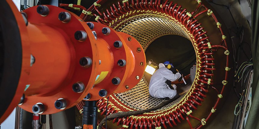
Before we can talk about rotating magnetic fields, we need to understand what we’re working with physically. I’ve found that the biggest “aha!” moments come when engineers can actually visualize the hardware, not just the theory.
Inside the Generator: A Three-Phase World
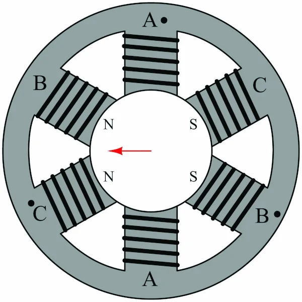
Let me walk you through what’s inside that cylindrical generator housing. If you could peek inside and look down the shaft from one end, you’d see something that looks remarkably like a clock face – and that’s exactly the analogy I want you to keep in mind.
Clock Face: Rotor at the Center | Stator Windings at the Circumference
The stator (the stationary outer part) contains three separate sets of copper windings. These aren’t randomly placed – they’re positioned exactly 120 degrees apart around the circumference. Why 120 degrees? Simple math: 360 degrees ÷ 3 phases = 120 degrees per phase.
Using our clock face analogy:
Phase A windings are positioned at 12 o’clock
Phase B windings are at 4 o’clock
Phase C windings are at 8 o’clock
Each of these positions represents not just one coil, but a group of windings distributed around that area of the stator.
More Than Just Three Electromagnets
Here’s where I see a lot of confusion, even among experienced technicians. When I say “Phase A is at 12 o’clock,” I don’t mean there’s just one coil sitting at that position. Each phase consists of multiple coils distributed around its section of the stator.
Think of it like this: instead of having three concentrated electromagnets, we have three regions of electromagnets. Phase A might have coils at 11 o’clock, 12 o’clock, and 1 o’clock positions. Phase B has coils distributed around the 4 o’clock region, and Phase C around the 8 o’clock region.
This distributed arrangement is crucial because it creates a much smoother, more uniform magnetic field. If we just had three concentrated coils, the magnetic field would be lumpy and irregular. The distributed windings give us that smooth, sinusoidal field pattern we need for efficient operation.
The Center Stage: The Rotor
In the center of our “clock face” sits the rotor – the part that actually spins. During startup, this rotor has its own separate DC-powered electromagnets fed by the excitation system. This creates a strong, constant magnetic field in the rotor – essentially turning it into a powerful permanent magnet.
The rotor’s magnetic field doesn’t change strength or polarity during operation – it’s steady DC. All the action happens in the stator windings, where we’ll be creating our rotating magnetic field.
The Birth of Rotating Magnetic Field
Now that you can visualize the physical layout – three sets of distributed windings positioned 120 degrees apart around a stationary stator, with a magnetized rotor in the center – we’re ready to explore how electrical timing creates the rotating magnetic field that makes it all work.
Imagine you’re watching three kids on swings at a playground. All three swings move back and forth with the same rhythm – same speed, same distance. But here’s the key: they don’t all reach their highest point at the same time. Let’s say Sarah (Phase A) reaches her highest point first. Exactly one-third of a swing cycle later, Mike (Phase B) reaches his highest point. Another third of a cycle later, Lisa (Phase C) reaches hers. Then the pattern repeats – Sarah, Mike, Lisa, Sarah, Mike, Lisa…
Here’s what this timing looks like in electrical terms:
At time zero:
Phase A is at its positive peak (+100%)
Phase B is at negative half-value (-50%)
Phase C is at negative half-value (-50%)
One-third cycle later:
Phase A has dropped to negative half-value (-50%)
Phase B reaches its positive peak (+100%)
Phase C is still at negative half-value (-50%)
Another third cycle later:
Phase A remains at negative half-value (-50%)
Phase B has dropped to negative half-value (-50%)
Phase C reaches its positive peak (+100%)
Rotating Magnetic Field: Electrical Phase Sequence
What we’ve created is electrical choreography. Three separate electrical phases, feeding three separate sets of windings, positioned 120 degrees apart both in space and time. The result? A single magnetic field that rotates continuously around the stator, ready to grab onto our magnetized rotor and start pulling it along.
The Emergence of Rotation
Now comes the magical moment where electrical timing meets physical positioning. The three stator windings, positioned 120 degrees apart around the circumference, receive these time-displaced currents. At any given moment, the three windings are energized with different current levels, creating three different magnetic field strengths pointing from three different spatial locations.
Consider a specific instant in time: when Phase A carries maximum current, it creates the strongest magnetic field pointing along its axis. Simultaneously, Phases B and C, carrying lesser currents in the opposite direction, create weaker fields pointing along their respective axes.
Rotor Follows the Resultant Rotating Magnetic Field Created by the Stator Winding
The mathematical beauty of the 120-degree spacing ensures these fields combine to create one resultant field that appears to rotate smoothly around the stator circumference. As the electrical phases progress through their sinusoidal cycles, the relative strengths of the three individual fields change continuously, causing the resultant field to rotate at a constant angular velocity.
The Continuous Rotation Principle
The key insight is that the rotating field doesn’t actually involve any physical rotation of the windings themselves. Instead, it’s the electrical excitation pattern that creates the illusion of rotation. The magnetic field strength and direction change continuously as the three-phase currents cycle through their predetermined pattern.
This rotating magnetic field maintains constant magnitude while its direction rotates at variable speed during turbine start up, determined by the frequency of the electrical supply and the number of pole pairs in the machine.
The Rotor’s Response to the Rotating Magnetic Field
The rotor’s behavior during gas turbine starting is fundamentally different from typical motor operation. Unlike an induction motor that relies on induced currents, the synchronous generator rotor operates as a powerful electromagnet, creating the magnetic coupling necessary for controlled starting.
Creating the Rotor Electromagnet
DC current flows through the rotor windings via slip rings and brushes, creating a constant magnetic field with clearly defined north and south poles. This DC excitation transforms the rotor into a powerful electromagnet—imagine a massive bar magnet spinning inside the stator.
The strength of this electromagnet depends on the amount of DC current supplied to the rotor windings. During starting, this current is carefully controlled to provide sufficient magnetic field strength for reliable coupling with the stator’s rotating field.
The Magnetic Chase
When the rotor electromagnet encounters the rotating magnetic field from the stator, basic magnetic principles take over. Opposite poles attract, like poles repel. The rotor’s magnetic poles attempt to align with the opposite poles of the stator’s rotating field.
Rotor’s Magnetic Chase Creates the Driving Torque
Here’s where the magic happens: since the stator field continuously rotates, the rotor never quite catches up to perfect alignment. Instead, it maintains a slight angular lag behind the rotating field—typically 10-30 degrees during starting conditions. This angular displacement creates the continuous torque that drives the rotor.
Torque Production Mechanism
The torque arises from the rotor’s constant attempt to minimize the magnetic reluctance between its poles and the stator field. Think of it as magnetic tension—the rotor experiences a continuous pulling force that tries to reduce the angular separation between the magnetic fields.
The magnitude of this torque depends on three factors:
Strength of the rotor’s magnetic field (controlled by DC excitation)
Strength of the stator’s rotating field (controlled by LCI output)
Angular displacement between the two fields
Smooth Acceleration Characteristics
This magnetic coupling provides inherently smooth acceleration because the torque production is continuous and predictable. Unlike mechanical starting methods that involve clutches or gear systems, the electromagnetic coupling has no physical contact points or sudden engagement moments.
The rotor accelerates smoothly from zero speed, maintaining its angular lag behind the stator field throughout the acceleration process. As the LCI gradually increases frequency, the rotor follows obediently, much like a compass needle following a moving magnet.
Load Angle Dynamics
The angular displacement between rotor and stator fields—called the load angle—automatically adjusts to provide the exact torque needed at each moment. During initial acceleration with high inertia loads, the load angle increases to generate maximum torque. As the rotor approaches synchronous speed, the load angle naturally decreases.
This self-regulating characteristic makes the starting process remarkably stable. The rotor cannot “lose sync” with the rotating field as long as the acceleration rate remains within reasonable limits.
Synchronous Speed Achievement
As the rotor reaches synchronous speed, the load angle approaches zero degrees. At this point, the rotor poles are nearly aligned with the stator field poles, and the system is ready for grid synchronization. The rotor now rotates at exactly the same speed as the stator’s magnetic field, completing the transformation from motor operation back to generator mode.
The entire process demonstrates the elegant simplicity of electromagnetic principles: a DC-excited rotor chasing a rotating AC field, creating the smooth, controlled motion necessary for reliable gas turbine starting.
The Role of Variable Frequency Control
A gas turbine rotor at standstill faces enormous inertia. If we applied full 60 Hz power directly, the rotating magnetic field would spin at 3,000 RPM while the rotor remains stationary.
The Load Commutated Inverter (LCI) solves this fundamental problem by controlling the frequency of the power supplied to the stator windings, effectively controlling the speed of the rotating magnetic field. LCI serves as the conductor of this electrical orchestra, orchestrating the precise frequency control that makes gas turbine starting possible.
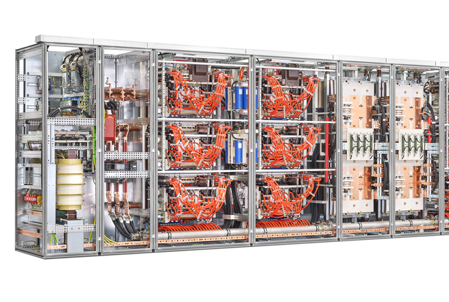
LCI Panel
Low-Frequency Launch
During startup, the LCI begins with extremely low frequency output—typically starting around 2-5 Hz. This creates a slowly rotating magnetic field that moves at roughly 120-300 RPM, giving the massive rotor time to electromagnetically couple with the field and begin following its rotation.
At these low frequencies, the rotor can physically keep pace with the magnetic field. The electromagnetic forces remain strong enough to provide starting torque while avoiding the excessive current draw that would occur at higher frequencies.
Controlled Acceleration
As the rotor gains momentum and begins rotating, the LCI gradually increases the output frequency. This acceleration follows a carefully programmed ramp rate, typically increasing at 2-3 Hz per second, depending on the specific turbine characteristics and loading conditions.
The beauty of this approach lies in maintaining synchronism between the magnetic field and the rotor throughout the acceleration process. The rotor never “sees” a rapidly moving field—instead, it experiences a gradually accelerating magnetic environment that it can follow smoothly.
Frequency-Torque Relationship
The LCI doesn’t just control speed; it manages the delicate balance between frequency and voltage to maintain optimal starting torque. As frequency increases, the voltage must be adjusted proportionally to prevent magnetic saturation of the stator core and to maintain the proper flux levels for efficient torque production.
This V/f (voltage-to-frequency) ratio control ensures consistent magnetic field strength throughout the acceleration process, providing steady torque characteristics from startup through synchronous speed.
Reaching Synchronous Speed
The acceleration continues until the rotor reaches synchronous speed—3,000 RPM for a 50 Hz, two-pole machine. At this point, the LCI output frequency matches the grid frequency, and the system is ready for synchronization with the electrical grid.
The entire process typically takes 5-10 minutes for a large gas turbine, transforming a stationary 100-ton rotor into a machine spinning at 60 revolutions per second with surgical precision.
Practical Benefits
This variable frequency starting method offers several critical advantages:
Reduced starting current: Current draw remains within acceptable limits throughout the process
Smooth acceleration: No mechanical shock or stress on turbine components
Controlled torque: Consistent starting torque regardless of rotor position
Grid protection: No disruptive current surges that could affect grid stability
The LCI essentially allows us to “dial in” the exact rotational speed we need at any moment, providing the controlled environment necessary for reliable gas turbine starting. This technology has revolutionized power plant operations, making remote startup possible and reducing the mechanical stress associated with traditional starting methods.
Real Implication: Turbine Starting System Configuration
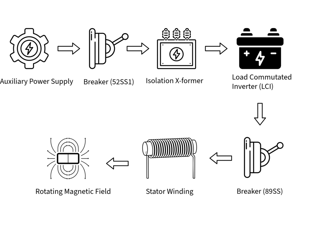
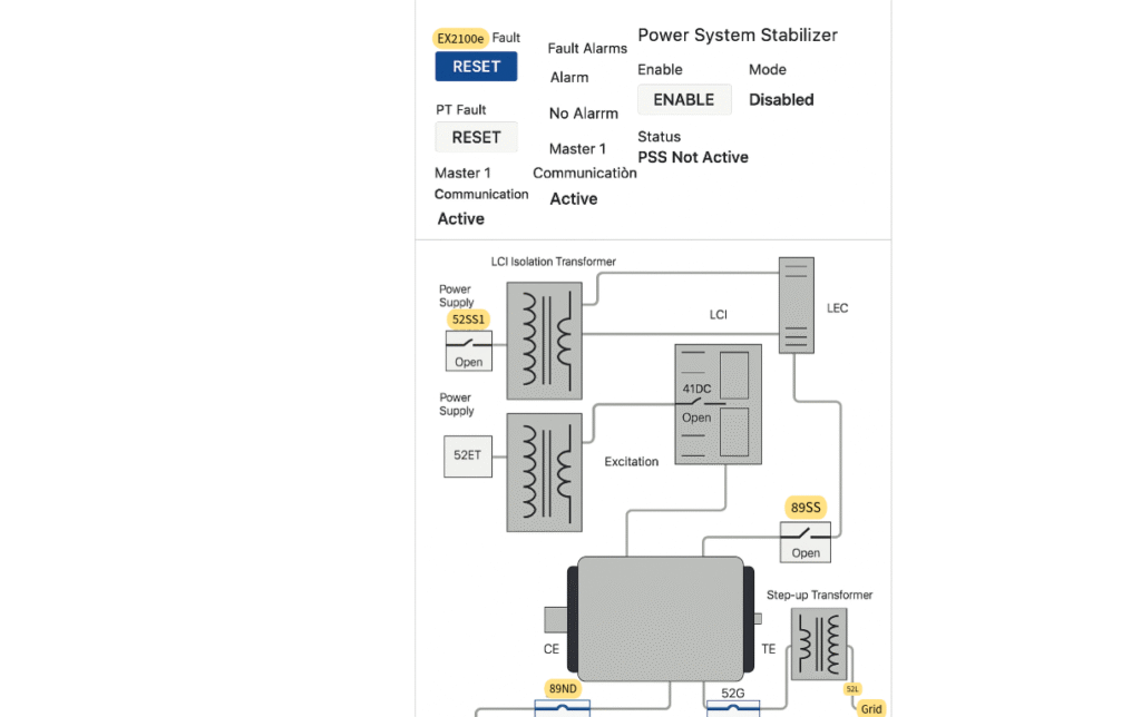
By explaining a real world control system diagram illustrated here for the complete electrical configuration during gas turbine starting operations, I’ll show you how auxiliary power systems coordinate to transform the generator into a starting motor.
Generator-Exciter-LCI Starting Control System
Power Supply Configuration
The starting process begins with auxiliary AC power from two independent (typically auxiliary power) sources feeding through isolation and excitation transformers. The 52SS1 breaker closes to energize the primary starting circuit, while 52ET provides power to the excitation system. This dual-feed arrangement ensures reliable starting power and maintains system redundancy.
LCI Operation Path
Auxiliary AC power flows through the isolation transformer to the Load Commutated Inverter (LCI). The LCI performs a two-stage conversion process:
AC to DC conversion: Input AC power is first rectified to DC
DC to variable AC conversion: The DC power is then inverted back to AC with precisely controlled frequency and voltage
This variable frequency AC output connects directly to the generator stator windings, creating the rotating magnetic field that drives starting torque. The LCI’s ability to start with low frequency (2-5 Hz) and gradually increase to synchronous frequency (50 Hz) enables smooth acceleration from zero speed.
Excitation System Circuit
Simultaneously, the excitation path energizes through breaker 52ET and the excitation transformer. The 41DC contactor closes during startup, connecting the exciter to the auxiliary power supply. The exciter converts the AC auxiliary power to DC current, which flows through slip rings to the generator rotor windings.
This DC excitation creates the powerful electromagnet within the rotor, establishing the magnetic poles necessary for electromagnetic coupling with the stator’s rotating field.
Starting Sequence Coordination
The beauty of this system lies in its coordinated operation:
Stator energization: LCI creates the rotating magnetic field in the stator windings
Rotor excitation: DC current creates electromagnetic poles in the rotor
Magnetic coupling: The rotor electromagnet follows the rotating stator field
Controlled acceleration: LCI frequency ramping provides smooth speed control
Transition to Self-Sustaining Operation
Once the gas turbine reaches self-sustaining speed and fuel ignition is established, the starting system disconnects automatically. The 89SS breaker opens, isolating the starting power circuit from the isolation transformers. At this point, the turbine’s mechanical energy drives the rotor, and the generator transitions from motor mode to power generation mode.
The 52G breaker remains open during starting and closes only after successful synchronization with the electrical grid, completing the transformation from starting motor back to electrical generator.
System Protection Features
The diagram shows several protective elements including the Power System Stabilizer (PSS) and various fault monitoring systems. These ensure safe operation during the critical starting phase and provide automatic shutdown capabilities if abnormal conditions are detected.
This configuration demonstrates the sophisticated electrical control required to reliably start large gas turbines, transforming a 100+ ton stationary rotor into a synchronized power generator through precise electromagnetic control.
Once the gas turbine reaches approximately 95% of rated speed, the combustion process becomes self-sustaining. The compressor now generates sufficient airflow and pressure to maintain combustion without external assistance. At this critical point, the turbine begins producing more mechanical power than required to drive the compressor, creating excess energy available for electrical generation.
Starting Circuit Disconnection
The control system monitors turbine speed and exhaust gas temperature to determine the optimal moment for starting circuit disconnection. When conditions are confirmed, the starting switches open, disconnecting the LCI and motoring power supply from the generator stator windings.
This disconnection occurs smoothly because the rotor is already rotating at near-synchronous speed with minimal load angle. The electromagnetic coupling between rotor and stator fields remains intact, but the energy flow direction is about to reverse.
Role Reversal
The beauty of the synchronous generator lies in its bidirectional nature. The same magnetic field interactions that created mechanical torque during starting now generate electrical power during normal operation. The physical hardware remains identical—only the energy flow direction changes.
Instead of electrical power creating mechanical rotation, mechanical rotation now creates electrical power. The rotor, now driven by turbine torque rather than electromagnetic forces, begins to lead the stator field slightly instead of lagging behind it.
Grid Synchronization
Before connecting to the electrical grid, the generator must match three critical parameters:
Frequency: Must equal grid frequency (60 Hz)
Voltage: Must match grid voltage levels
Phase: Must align with grid phase rotation
Modern control systems perform this synchronization automatically, making fine adjustments to turbine speed and generator excitation until all parameters align within acceptable tolerances.
Power Generation Mode
Once synchronized and connected to the grid, the generator transitions to its primary role as a power producer. The load angle—previously used to create starting torque—now determines the amount of electrical power generated. As the turbine governor increases fuel flow and mechanical power, the load angle increases proportionally, generating more electrical output.
The transition is complete. The same rotating magnetic field that enabled starting now facilitates power generation, demonstrating the fundamental reversibility of electromagnetic energy conversion. The gas turbine has successfully transformed from a stationary machine into a synchronized power generator, ready to supply electrical energy to the grid.
Conclusion: The Bigger Picture
The rotating magnetic field principles demonstrated in gas turbine starting extend far beyond power plant operations. These fundamental electromagnetic concepts form the backbone of virtually every rotating electrical machine in modern industry.
For engineers and technicians, grasping these fundamentals enables better troubleshooting, system design, and operational decisions. When you understand how rotating magnetic fields create torque, you can predict motor behavior, optimize starting sequences, and diagnose problems across diverse applications.
The elegance lies in the universality—from the smallest servo motor to the largest power plant generator, the same electromagnetic principles govern operation. Master these concepts in one application, and you’ve gained insight into the entire world of rotating electrical machinery.


4 Comments
Comments are closed.