How Hydrogen Cooled Generators Work: Safety Engineering and Common Troubleshooting
Welcome Back!
In our previous post, we explored why 98% of power plants choose hydrogen over air for generator cooling. We covered the compelling advantages – superior heat transfer, reduced windage losses, fire suppression properties, and the impressive efficiency gains that make hydrogen the clear winner in our decision matrix.
But here’s what I hear most from new engineers and operators visiting our control rooms: “Okay, I get why hydrogen is better, but how does this actually work in practice? What does the system look like? How do we keep it safe?”
Those are exactly the right questions to ask.
That’s what we’re covering today. We’re going inside the hydrogen cooled generator – literally. I’ll walk you through the actual hardware, the flow paths, the safety systems that protect you and the equipment, and the real-world performance data from generators I’ve worked with over the years.
We’ll also tackle the troubleshooting scenarios you’ll inevitably face – because in my experience, it’s not a matter of if you’ll deal with hydrogen purity issues or pressure problems, but when. And when that moment comes, you’ll want to know exactly what to do.
Ready to dive into how hydrogen cooled generators work in practice? Let’s get started.
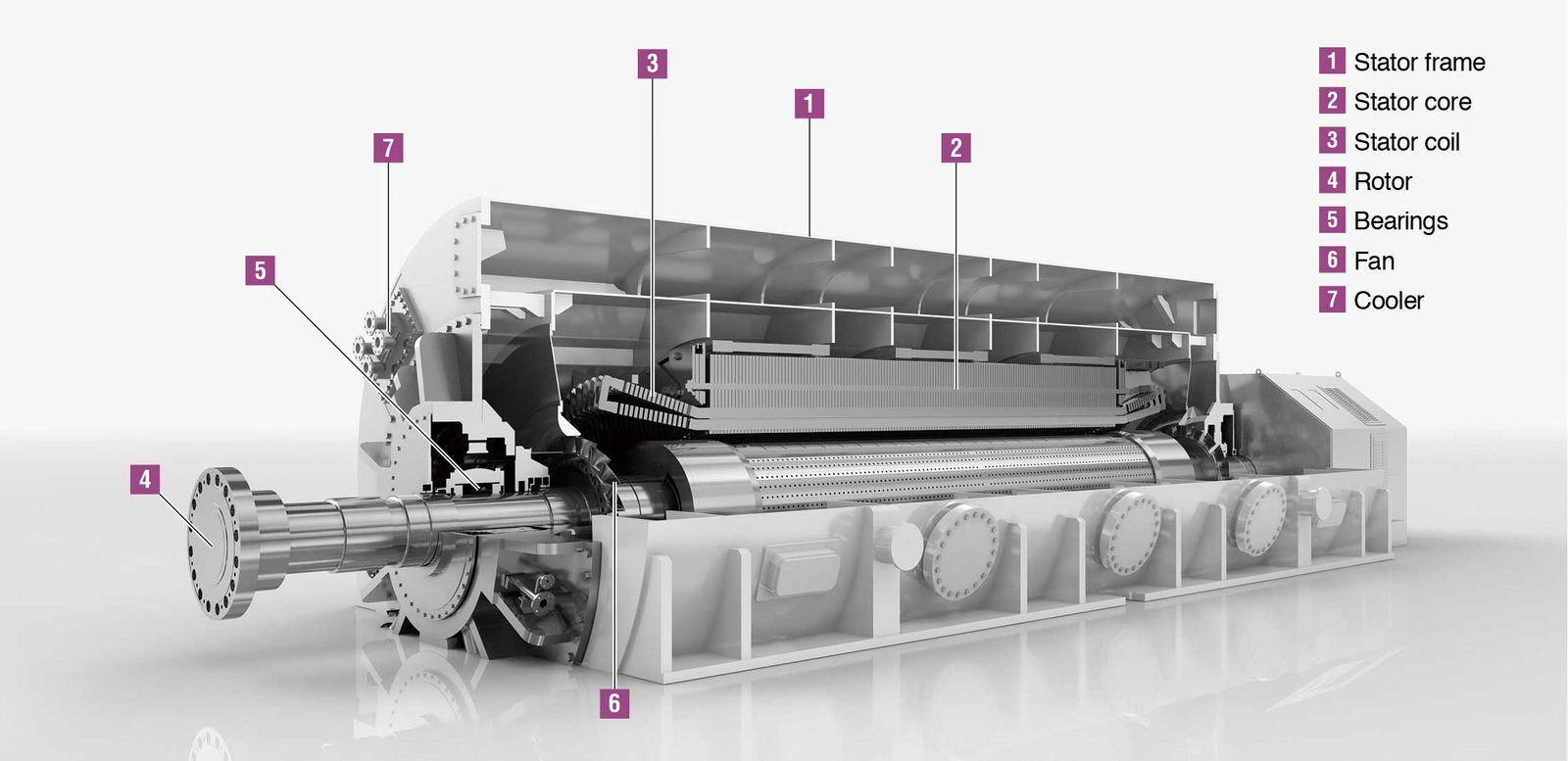
Inside the Hydrogen Cooled Generator: Core Components
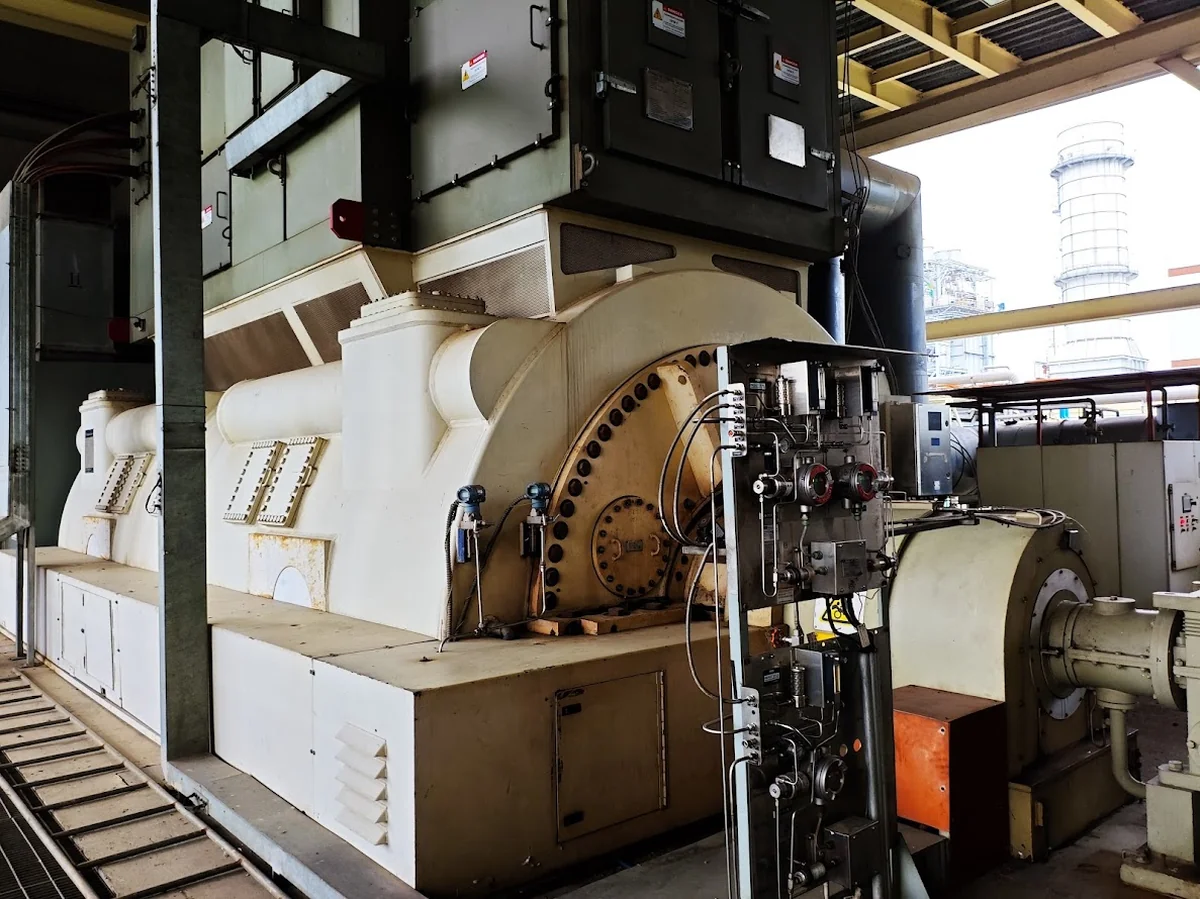
Let me walk you through exactly how these systems work. Think of it like this – you’ve got a massive electrical machine generating hundreds of megawatts, and all that power generation creates serious heat. We’re talking about enough heat to literally melt copper windings if we don’t get it out efficiently. Here’s how we do it. Walk with me.
System Architecture: The Sealed Universe
Picture the generator as a giant sealed thermos bottle, but instead of keeping your coffee hot, we’re keeping hydrogen in and air out. The entire generator sits inside what we call the generator housing – a robust steel casing that’s completely gas-tight. This isn’t just any seal job; we’re talking about precision engineering here because even tiny leaks can cause big problems.
Inside this sealed world, hydrogen circulates continuously. It’s like having a dedicated air conditioning system, but instead of air, we’re using hydrogen as our cooling medium. The hydrogen picks up heat from the generator’s hot spots and carries it away to heat exchangers where we dump that heat into our water cooling system.
The beautiful thing about this setup is that it’s a closed loop. The same hydrogen keeps circulating – we’re not constantly consuming it. We just need to maintain the right pressure and purity, and the system does its job day after day.
The Cooling Circuit: Three-Dimensional Heat Highway
Now, here’s where it gets interesting. The hydrogen doesn’t just slosh around randomly – it follows very specific paths designed to grab heat exactly where it’s generated.
Let’s start with the rotor. As it spins at 3,600 RPM (for 60 Hz systems), centrifugal force pushes hydrogen outward through radial cooling ducts. These ducts are machined right into the rotor body, running from the center outward like spokes on a wheel. The hydrogen flows out through these ducts, picks up heat from the rotor windings, then gets flung outward by centrifugal force.
The stator cooling is different but equally clever. Here, we use axial cooling passages – think of them as channels that run parallel to the generator’s axis. Hydrogen flows through these passages, running alongside the stator windings where the heat is being generated. The key is getting the hydrogen as close as possible to the copper conductors where the I²R losses are creating heat.
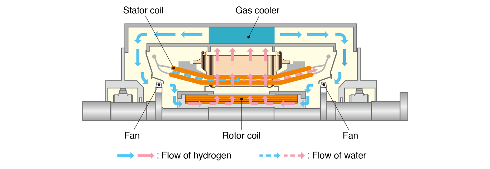
To truly understand this system, imagine looking at a cutaway view of the generator:
- Horizontal Plane (Looking Down): You’d see hydrogen flowing radially outward from the rotor center, like water flowing through the spokes of a spinning wheel.
- Vertical Plane (Side View): You’d see hydrogen flowing axially through the stator, like multiple rivers flowing parallel to each other along the generator’s length.
What makes this three-dimensional? The heated hydrogen from both the rotor and stator has to find its way to the heat exchangers. We use fans mounted on the rotor shaft to create circulation patterns that sweep the hot hydrogen away from the windings and push it toward the coolers. It’s like having a sophisticated ventilation system that’s spinning at 3,600 RPM.
Heat Exchangers and External Cooling: The Thermal Cascade
Here’s where we get that heat out of the hydrogen and into our plant’s cooling water system. The heat exchangers – we usually call them hydrogen coolers – are typically mounted on the outside of the generator housing.
Hot hydrogen enters these coolers and flows through a series of tubes or passages. On the other side of these tubes, we’ve got cooling water flowing. The hydrogen gives up its heat to the water through the tube walls, and now we’ve got cool hydrogen ready to go back into the generator.
This is what I call the “cascade effect” – it’s like a relay race for heat removal:
- First leg: Hydrogen picks up heat from the generator windings
- Second leg: Water picks up heat from the hydrogen in the heat exchangers
- Third leg: Cooling tower or river water picks up heat from the cooling water
Each step in this cascade is crucial. If your cooling water temperature goes up because of a hot day or cooling tower issues, your hydrogen temperature goes up, and ultimately your generator temperature goes up. Everything’s connected.
The flow rates matter too. We typically size these systems so the hydrogen makes several complete circuits through the generator every minute. The cooling water flow is adjusted to maintain hydrogen temperature within specification – usually around 40-50°C at the cooler outlet.
Pressure System Design: The Positive Pressure Strategy
This is probably the most critical aspect that new engineers need to understand: we always maintain positive pressure in the hydrogen system. Always. Typically 15-30 psi above atmospheric pressure, depending on the specific generator design.
Why positive pressure? Two reasons that are absolutely crucial:
First, it prevents air from leaking into the system. Even tiny amounts of air contamination can create explosive mixtures with hydrogen. By keeping the hydrogen pressure higher than atmospheric pressure, any small leaks will be hydrogen leaking out, not air leaking in.
Second, positive pressure gives us better heat transfer. Higher pressure means denser hydrogen, which means better heat capacity and thermal conductivity. It’s like the difference between trying to cool something with thin mountain air versus thick sea-level air.
The pressure system includes a supply source (either cylinders or an on-site generation system), regulators, relief valves, and monitoring equipment. We’ve got pressure transmitters at multiple points, and if pressure drops below setpoint, alarms start going off. In my experience, pressure alarms are often your first indication that something’s not right – maybe a developing leak, maybe a supply system issue. When you see pressure dropping, that’s not just a number on a gauge – that’s your safety margin disappearing.
You can learn more about design and development of large hydrogen cooled generators here: https://power.mhi.com/randd/technical-review/pdf/index_14e.pdf
Safety Engineering: Making Hydrogen Safe
Let me be completely straight with you about hydrogen safety – because if I’m not honest about the risks, I’m not doing my job as an engineer.
The Fundamental Safety Challenge
Hydrogen can explode. There’s no sugar-coating that fact. Mix it with air in the wrong proportions (4-75% hydrogen by volume), add a spark, and you’ve got a serious problem. I’ve seen the aftermath of hydrogen incidents, and they’re not pretty.
But here’s the thing – and this is what experience has taught me – hydrogen isn’t inherently dangerous when you engineer the systems properly. It’s predictable. It follows the laws of physics. And if you respect those laws and design your systems accordingly, you can make hydrogen as safe as any other industrial process.
The key is understanding that hydrogen safety isn’t about eliminating risk – it’s about controlling it through multiple layers of engineering safeguards. I always tell new engineers: “Think of it like working with electricity. High voltage can kill you, but we work with it safely every day because we understand it, we follow procedures, and we use proper equipment. Same principle with hydrogen.”
Multiple Barriers Approach
We use what I call the “belt and suspenders and safety rope” approach – multiple independent barriers that all have to fail before you get into trouble. It’s the same defense-in-depth philosophy they use in nuclear plants, and it works.
First Barrier: Sealed Systems The primary defense is keeping hydrogen where it belongs – inside the generator. This is where the sealing oil system becomes absolutely critical. Let me explain why.
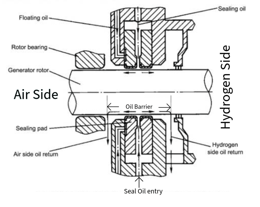
The generator shaft has to come out of the hydrogen-filled housing, right? That’s where the coupling connects to the turbine. But you can’t just have the shaft poking through a hole – that would be a massive leak path. So we use a sealing oil system that creates a liquid barrier between the hydrogen and the outside world.
Here’s how it works: We inject oil under pressure at the point where the shaft exits the generator housing. This oil flows in both directions – some flows into the hydrogen space (and gets collected and cleaned), and some flows out to atmosphere. This means you never have hydrogen directly contacting air – there’s always an oil barrier in between. The oil pressure is carefully controlled to be higher than the hydrogen pressure, which prevents hydrogen from escaping along the shaft.
Don’t Confuse Oil Seals and Sealing Oil System!
When we talk about oil seals and the sealing oil system, we’re referring to two related—but very different—concepts. Think of oil seals (sometimes called shaft seals) as the mechanical components—the physical parts that sit around the generator shaft, where it exits the casing. Their job is simple: block hydrogen from leaking out and stop contaminants (like air) from sneaking in. Now, these seals alone aren’t enough. That’s where the sealing oil system comes in—it’s the supporting system that pumps high-pressure oil into those seals. This oil creates a sort of buffer zone that keeps the hydrogen inside the generator casing by always maintaining higher pressure than the gas. So yes, oil seals are part of the sealing oil system, but they’re like the gate, while the sealing oil is the pressure force behind the gate.
Second Barrier: Detection Systems Even with perfect sealing, we assume some hydrogen might escape. That’s why we have gas detection systems throughout the generator area. These aren’t just simple alarms – they’re sophisticated monitoring systems with multiple sensors at different elevations.
Why different elevations? Because hydrogen is lighter than air. If it leaks, it rises. So we put detectors up high where hydrogen would accumulate, and we set them to alarm at very low concentrations – typically 1% hydrogen in air, which is way below the explosive limit.
The detection system does more than just alarm. At certain concentration levels, it automatically starts ventilation fans to clear any hydrogen accumulation. At higher levels, it can shut down electrical equipment that might create sparks.
Third Barrier: Automatic Responses If the first two barriers fail, the system protects itself. High hydrogen concentration triggers automatic actions: ventilation systems activate, electrical equipment shuts down, and emergency procedures kick in.
The generator protection system is also watching. If hydrogen pressure drops suddenly (indicating a major leak), the system can automatically reduce generator loading or even trip it offline if necessary.
Purging and Inerting Systems
This is where a lot of people get confused, but it’s actually straightforward once you understand the principle. The problem is that you can’t go directly from air to hydrogen or vice versa – you’d create explosive mixtures in the process.
Let me paint a picture: Say you’ve got a generator full of air, and you start pumping in hydrogen. As the hydrogen concentration increases, you’re going to pass through that explosive range (4-75% hydrogen). That’s unacceptable.
So we use CO₂ as a “safety bridge.” Here’s the sequence:
Startup purging:
- Start with air in the generator
- Purge with CO₂ to displace all the air
- Verify CO₂ purity (we test to make sure there’s no oxygen left)
- Purge with hydrogen to displace the CO₂
- Verify hydrogen purity before energizing
Shutdown purging:
- Start with hydrogen in the generator
- Purge with CO₂ to displace the hydrogen
- Verify CO₂ purity (make sure no hydrogen remains)
- Purge with air to displace the CO₂
- Now it’s safe to open up for maintenance
The beauty of CO₂ is that it won’t burn or explode with anything. It’s inert. So CO₂ mixed with air is safe, CO₂ mixed with hydrogen is safe, and pure CO₂ is safe. It’s the perfect intermediate step.
The purging process takes time– usually several hours for a complete cycle. Don’t try to rush this process, that’s when accidents happen. The gas analyzers need to show proper purity at each step before you proceed. No shortcuts.
During purging, we also monitor the process with continuous gas analysis. We’re not just pumping gas– we’re measuring O₂, CO₂, and H₂ concentrations throughout the process to make sure everything’s going according to plan.
Remember: hydrogen safety isn’t about being afraid of the gas – it’s about understanding it, respecting it, and using proper engineering controls to manage the risks. Do that, and you’ll have a long, safe career working with these systems.
Common Issues and Troubleshooting
Every hydrogen cooling system will eventually have problems. Here’s what to watch for and how to fix it, based on real field experience.
1. Hydrogen Purity Problems
What you’ll see: Generator temperatures creeping up, cooling efficiency dropping, purity analyzer showing contamination alarms.
Why it happens: Air leaks in (bad seals), moisture gets in (condensation or water leaks), or your hydrogen supply is contaminated.
How to diagnose: Check your purity analyzer readings first. Normal hydrogen purity should be 98%+. If it’s lower, start with leak detection around seals and connections. Look for moisture in the system – condensation in coolers is a common culprit.
Fix it: For minor contamination, purge with fresh hydrogen. For persistent problems, replace seals and check your supply system. Always verify purity before declaring victory.
Prevent it: Check purity daily during rounds. Maintain sealing oil systems properly. Don’t ignore small leaks – they become big problems.
2. Pressure System Issues
Low Hydrogen Pressure
What you’ll see: Pressure alarms, generator temperatures rising, reduced cooling performance.
Why it happens: Usually a supply problem (empty cylinders, failed regulator) or a major leak somewhere in the system.
How to diagnose: Check supply pressure first – that’s the most common cause. If supply is good, walk the system looking for obvious leaks. Use your ears – hydrogen leaks often make a distinct hissing sound. Use gas detectors in every joints.
Fix it: Replace empty hydrogen cylinders or fix supply system issues. For leaks, isolate and repair. Don’t just keep adding hydrogen to compensate for leaks.
Pressure Fluctuations
What you’ll see: Pressure gauge bouncing around, intermittent alarms, unstable system behavior.
Why it happens: Regulator problems, unstable supply, or partial blockages in the system.
Fix it: Check regulator calibration and operation. Verify supply system stability. Clear any blockages in lines or filters.
3. Cooling System Performance Issues
High Generator Temperatures
What you’ll see: Temperature alarms, reduced generator output capability, hot spots on thermal imaging.
Why it happens: Not enough hydrogen flow (fan problems), blocked coolers, or heat exchanger issues.
How to diagnose: Check hydrogen flow rates and fan operation. Use thermal imaging to find hot spots. Look for blocked cooler passages or reduced cooling water flow.
Fix it: Clean blocked coolers, repair or replace fans, check cooling water system. Sometimes it’s as simple as cleaning debris from cooler fins.
Uneven Cooling Distribution
What you’ll see: Temperature variations across windings, hot spots in specific areas, thermal imbalances.
Why it happens: Flow maldistribution, partial blockages, or damaged internal baffles directing hydrogen flow.
Fix it: Usually requires internal inspection during outages. Check and repair flow baffles, clear blockages, ensure proper hydrogen distribution.
4. Safety System Malfunctions
Gas Detection System Issues
What you’ll see: False alarms, detection system failures, nuisance trips.
Why it happens: Sensor contamination, calibration drift, electrical connection problems.
Fix it: Clean sensors with appropriate solvents, calibrate with known gas samples, check electrical connections. Replace sensors if they’re beyond calibration limits.
Ventilation System Problems
What you’ll see: Inadequate air changes, hydrogen accumulation alarms, poor ventilation performance.
Why it happens: Ventilation fans fail, dampers stick, or ductwork gets blocked.
Fix it: Test fan operation, check damper movement, clear ductwork obstructions. Verify proper air flow rates with measurements.
5. Leakage Detection and Management
Internal Leaks (stator to rotor)
How to detect: Monitor pressure differential between stator and rotor spaces. Look for unusual thermal patterns.
What to do: Reduce generator load to minimize heating. Monitor continuously and plan for repair during next outage.
External Leaks (to atmosphere)
How to detect: Visual inspection, soap bubble test on suspected areas, electronic leak detectors.
What to do: Assess location and severity. Roof leaks are less critical than ground-level leaks. Isolate, purge, and repair following safety procedures.
6. Startup and Shutdown Issues
Purging Problems
What you’ll see: Incomplete air removal, contamination during gas transitions, extended purging times.
Fix it: Follow purging sequences exactly. Don’t rush – proper purging takes time. Verify each step with gas analysis before proceeding.
Pressure Building Issues
What you’ll see: Slow pressure rise, inability to reach operating pressure, system won’t hold pressure.
Fix it: Check supply system capacity and regulator operation. Verify all valves are properly positioned. Look for large leaks preventing pressure buildup.
7. Maintenance-Related Problems
Post-Maintenance Issues
What you’ll see: New leaks after seal replacement, purity problems after servicing, system instability.
Fix it: Double-check all connections and reassembly. Pressure test before filling with hydrogen. Follow proper startup procedures after maintenance.
Scheduled Maintenance Indicators
What to watch: Gradually increasing leak rates, declining purity trends, rising operating temperatures.
When to act: Don’t wait for failures. Schedule maintenance when trends indicate degrading performance.
8. Emergency Response Procedures
Major Leak Response
Immediate actions: Evacuate area, stop all ignition sources, increase ventilation, reduce generator load.
Next steps: Emergency shutdown if necessary, isolate the leak, notify emergency response team.
Fire/Explosion Risk Management
If detected: Activate fire suppression, evacuate personnel, emergency shutdown, call fire department.
Remember: Hydrogen fires are nearly invisible in daylight. Use thermal imaging or water spray to locate flames.
9. Diagnostic Tools and Techniques
Essential Instruments
Always have: Purity analyzer, pressure gauges, electronic leak detector, thermal imaging camera.
For advanced diagnosis: Flow meters, vibration analyzers, ultrasonic thickness gauges.
Data Analysis
Track trends: Purity levels, pressure stability, temperature patterns, leak rates.
Set baselines: Know what normal looks like so you can spot problems early.
10. When to Call for Help
Call immediately for: Major leaks, fire/explosion risks, safety system failures, any situation you’re not sure about.
Call for expert help: Persistent problems you can’t solve, unusual symptoms, major maintenance planning.
Have ready: System drawings, recent maintenance records, current operating parameters, description of symptoms and timeline.
Remember: It’s better to make an unnecessary call than to risk safety or equipment damage. When in doubt, ask for help.
Real-World Performance: Case Studies from the Field
Let me share two situations I’ve dealt with that taught me important lessons about hydrogen cooling systems. These aren’t textbook problems – they’re real issues that happened to real plants, and they show how theory meets reality.
Case Study 1: The Mysterious Temperature Rise
The Problem: I got called to a 350 MW unit where generator temperatures had been slowly climbing over three months. Nothing dramatic – just a degree here, a degree there. The operations team kept adjusting cooling water flow to compensate, but eventually they couldn’t keep up.
What Everyone Assumed: The obvious suspects were hydrogen purity (looked fine), cooling water temperature (normal), and hydrogen pressure (stable). The plant had recently done seal maintenance, so everyone figured maybe they didn’t get the seals quite right.
What I Found: The hydrogen purity analyzer was reading 98.5% – technically acceptable, but I’d seen this unit run at 99.2% before. That 0.7% difference seemed small, but it meant the hydrogen density was lower than optimal. The cooling efficiency was dropping just enough to cause the temperature creep.
The Real Culprit: Turns out the sealing oil system was running slightly low pressure after the maintenance. Not low enough to trigger alarms, but low enough to allow tiny amounts of air infiltration. Over three months, this gradually degraded the hydrogen purity.
The Fix: Adjusted sealing oil pressure to specification and did a controlled purge to restore hydrogen purity. Temperatures dropped back to normal within hours.
The Lesson: Small deviations from normal can have big consequences over time. Don’t just look at whether readings are “acceptable” – compare them to what’s normal for your specific unit. Those old logbooks aren’t just paperwork – they’re your baseline for what good performance looks like.
Case Study 2: The Leak That Wasn’t There
The Problem: A 500 MW unit kept triggering hydrogen detection alarms in the generator area. The alarms would come and go – sometimes multiple times per shift, sometimes quiet for days. The operations team was getting frustrated because they couldn’t find any leaks.
What Everyone Tried: They’d done multiple soap bubble tests, electronic leak detection sweeps, and even brought in outside contractors. Every time the alarm went off, they’d search the area and find nothing. Some people started thinking the detectors were faulty.
What I Discovered: I spent a full shift watching the pattern. The alarms always happened when the unit was changing load – either ramping up or down. That was the clue I needed.
The Real Issue: During load changes, the generator housing expands and contracts slightly due to temperature changes. This was causing a mechanical seal to leak intermittently – just enough to trigger the detector, but not enough to find with conventional methods.
The Fix: We identified the problematic seal during the next planned outage and replaced it. The intermittent alarms stopped completely.
The Lesson: Don’t dismiss patterns as coincidence. When problems happen at specific times or under specific conditions, that’s telling you something important about the root cause. Also, trust your instruments – that hydrogen detector was doing its job perfectly.
Conclusion: The Invisible Engineering Marvel
Here’s what strikes me after years of working with hydrogen cooling systems: most people walk past a power plant every day and have no idea there’s explosive gas spinning at 3,600 RPM just a few hundred feet away, keeping their lights on.
That’s the mark of truly great engineering – when something this complex works so reliably that it becomes invisible.
Think about what we’ve covered today. We’re circulating hydrogen through a massive rotating machine, extracting enormous amounts of heat, maintaining precise pressure and purity levels, and doing it all safely, day after day, year after year. The engineering that makes this possible didn’t happen overnight – it’s the result of decades of refinement, learning from mistakes, and continuous improvement.
~Rotormind


2 Comments
Comments are closed.